
Reverse Engineering
Reverse Engineering a Part With No Drawings: How the Process Works
No drawing, no CAD file, no manufacturer left to call — but you still need the part. How the reverse engineering process runs, from measurement to production CAD.
Reverse Engineering7 August 2026·By The Sarjan Solution Team
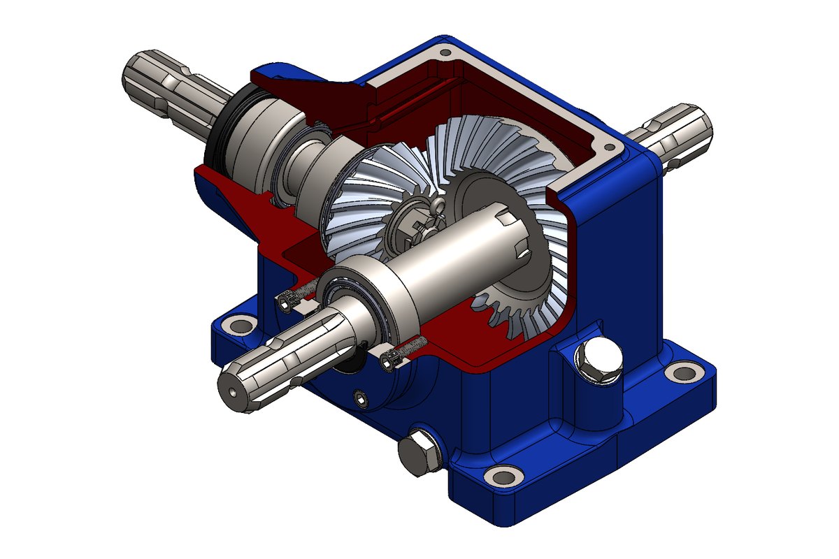
It’s a common situation: a machine needs a replacement part, the original vendor is gone, and no drawing or CAD file exists — only the worn physical part itself. Reverse engineering rebuilds the design from that part, step by step:
- Capture — the physical part is measured directly or 3D scanned to capture its geometry as a point cloud.
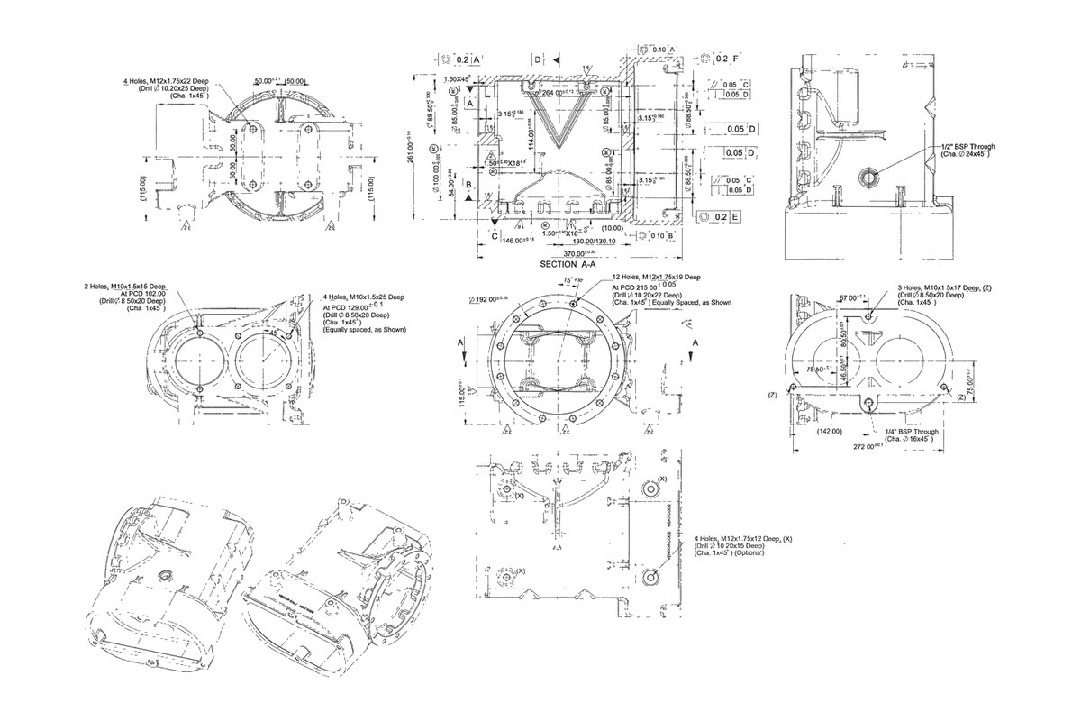
- Reconstruction — the point cloud is converted into a proper parametric CAD model (not just a mesh copy), so it can be edited, dimensioned, and manufactured from.
- Correction — worn or damaged features on the physical sample are identified and corrected in the model, so the reconstruction reflects the intended design, not its current wear state.
- Validation — the rebuilt model is checked against the physical part’s critical dimensions and, where relevant, against mating parts it needs to fit.
- Optimisation (optional) — once the part exists as an editable CAD model, it can be improved — a material change, a redesign for a new manufacturing process, or a fix for a known failure point.
The output is a real, editable CAD file — not a one-time 3D print copy — so the part can be manufactured, modified, or handed to a new vendor going forward.
Have a part that needs rebuilding? See our Reverse Engineering service or send us the details.
Measuring, scanning, or both
Not every part needs a 3D scanner. A part made of flats, holes and cylinders is often faster and more accurate to measure conventionally — calipers, height gauge, bore gauge, thread gauges — because those tools read the feature directly rather than inferring it from a surface.
Scanning earns its place on freeform geometry: castings, impellers, moulded shapes, worn surfaces. In practice many jobs use both — scan the organic surfaces, measure the precision features, then build one model from the two sources.
Deciding which dimensions actually matter
This is the judgement that separates useful reverse engineering from tracing. A worn shaft might measure 49.94 mm. It was almost certainly designed as 50 mm with a tolerance, and it has worn. Copying 49.94 into the drawing reproduces the wear as though it were intent.
The same applies to the many dimensions on a part that are simply how it was made rather than what it needs to be. Recognising which features are functional — which surfaces locate, seal or carry load — is what makes a reverse-engineered part manufacturable rather than merely accurate.
Tolerancing a part you did not design
You rarely know the original tolerances, so you infer them from function. A bearing seat gets a bearing fit. A clearance hole gets a clearance. A sealing face gets a surface finish the seal can work against. Everything else gets a sensible general tolerance rather than a tight one copied across from the critical features.
Over-tolerancing a reverse-engineered part is a common and expensive mistake — it makes a simple replacement part cost like a precision one for no functional gain.
Checking before you commit to manufacture
Where a physical sample exists, the model gets compared back against it before any metal is cut. If the part is one of an assembly, the surrounding components matter as much as the part itself — a replacement that is dimensionally perfect but does not fit its neighbours has not solved the problem.
See our reverse engineering service, or the textile machine project for how this runs on a full assembly.
SS
Written by the Sarjan Solution Team
CAD design & engineering consultancy, Ahmedabad & Gandhinagar — delivering CAD, simulation and product design services since 2018.
Keep Reading
More Insights
Ready To Engineer Your Next Product?
Send us your requirement with a brief description and we'll reach out with the best quote — usually within one business day.