
Manufacturing Support
Structural Steel Detailing Services
Fabrication and erection drawings for industrial steelwork — equipment support structures, access platforms, stairs and handrails, pipe and conveyor supports, skids, frames and building steel for plants. Member drawings, assembly drawings, connection details, bolt lists and material take-offs detailed in SolidWorks, Inventor or AutoCAD to the conventions your fabricator and engineer expect.
Service Overview
Steel Detailing For Fabricators, Engineers And Plant Builders
Steel detailing turns the engineer's design drawings into what the shop and the site crew need: every member drawn with its cuts, copes, holes and welds; every assembly with its parts and bolts; erection drawings with marks, orientations and sequence. We detail from your design drawings or 3D model, raise RFIs for anything unclear, and check every drawing against the design before it goes to the shop.
Our detailing sits alongside our machinery and fabrication work, so it suits industrial steel — equipment supports, platforms, mezzanines, stair towers, pipe racks, conveyor and chute supports and plant frames — detailed in the same CAD platforms we use for the equipment they carry.
- Fabrication (shop) drawings for beams, columns, bracing, plates and built-up members
- Assembly and erection drawings with piece marks, orientations and bolt callouts
- Connection detailing from the engineer's design: shear, moment and bracing connections
- Platforms, stairs, ladders, handrails and grating with anchor and base plate details
- Equipment support structures, skids, pipe and conveyor supports, plant frames
- Material take-offs, bolt lists, weld maps and NC/DXF plate profiles
What this service is not: We do not perform structural engineering design or connection design calculations; detailing is from your engineer's design, and connection capacities remain the engineer of record's responsibility.
What's Included
Steel Detailing Capabilities
Shop Drawings
Single-part and assembly drawings with cuts, copes, holes, welds, marks and material grades the fabricator needs to cut and weld.
Erection Drawings
Plans, elevations and sections with piece marks, orientations, bolt types and sequence notes for the site crew.
Connection Details
Bolted and welded connections drawn to the engineer's design, with gauges, edge distances and weld sizes checked against the standard.
Platforms & Access Steel
Mezzanines, platforms, stairs, ladders, handrails and grating with base plates and anchors.
Equipment Supports & Skids
Structures that carry machinery, pipework and conveyors, coordinated with the equipment models we design.
Lists & Shop Files
Material take-offs, bolt lists, weld maps and DXF plate profiles for cutting.
What We Need From You
Inputs We Work From
Send whatever you have. We list anything missing or ambiguous in a query sheet and agree it with you before modelling starts — nothing is assumed silently.
- Engineer's design drawings and specifications, or a design 3D model
- Connection design details or the standard connections to apply
- Steel grades, bolt types and your fabricator's preferences and limits
- Site information: grid, levels, anchor layouts and equipment interfaces
- Drawing template, marking scheme and the detailing standard your market uses
- Target CAD platform (SolidWorks, Inventor or AutoCAD) and delivery formats
What You Receive
Deliverables & File Formats
Drawings
- Shop drawings per member and assembly, with marks and material grades
- Erection drawings: plans, elevations, sections and details
- Connection details and base plate and anchor details
Lists
- Material take-off and bolt list
- Weld map and schedule
- Cut lists for profiles and plates
Files
- Native 3D model and drawings in SolidWorks, Inventor or AutoCAD
- DXF plate profiles for cutting; PDF drawing sets
- RFI log and check record
Native files in your platform and version (older versions on request), plus neutral STEP AP214/AP242, IGES, Parasolid, DXF and PDF as needed.
Standards & Platforms
Drawn To Your Standard, Delivered In Your CAD
We work to the drawing and design standards your market specifies. Editions below are current as of October 2026.
Standards we apply
- AISC conventions (USA) — Detailing practice consistent with AISC specifications; edition confirmed per project with your engineer
- AS/NZS 5131:2016 (Amd 1:2020) — Structural steelwork fabrication and erection documentation for Australia and New Zealand
- EN 1090 execution conventions (EU/UK) — Detailing aligned to the execution class and documentation your fabricator works to
- IS 800 / IS 2062 (India) — Indian structural steel design and material references
- AWS A2.4:2020 / ISO 2553:2019 — Weld symbols to the standard your fabricator reads
- ASME Y14.5 / ISO GPS — Dimensioning and tolerancing conventions on plates and machined interfaces
Native CAD platforms
You receive editable native files, not just exports. We do not advertise platforms we cannot deliver natively.
How The Work Runs
Our Process For This Service
Design review and RFIs
We review the design drawings, raise RFIs for gaps and agree marking, standards and templates; fixed price per structure or tonne.
3D model
The structure is modelled with members, connections and hardware so clashes and fit are checked before drawing.
Detail drawings
Shop and erection drawings, connection details and lists are produced on your template.
Check and issue
An independent check against the design and standard, then issue for approval and for fabrication with revision control.
Worked Example
Structural Guide Design
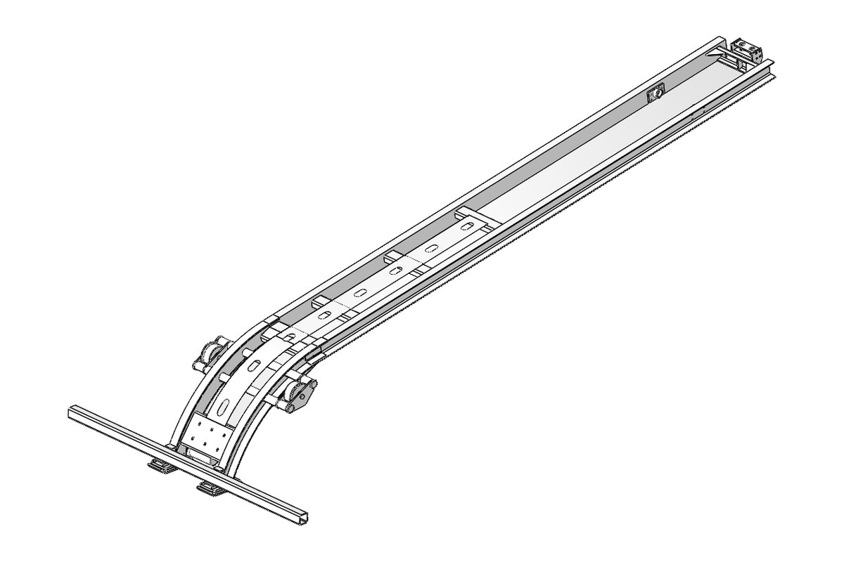
A structural guide assembly designed and detailed in SolidWorks — fabricated members, plates and connections with fabrication drawings, cut lists and a BOM delivered for the client's fabricator.
- Industry: Machine Building
- Software: SolidWorks
Engagement Models
Three Ways To Work With Us
Every quote states scope, deliverables, formats, standard, revision rounds and deadline. Prices are quoted per project — in USD, EUR, GBP, AUD or INR.
Fixed price per job
Best for defined scopes — a drawing set, a conversion batch, one analysis. You know the total before work starts.
Hourly with a cap
For evolving design work where scope is still forming. Hours are logged, reported weekly and never exceed the agreed cap without your sign-off.
Dedicated engineer
A named engineer reserved for your work, month by month, on your templates and in your CAD — an extension of your own design office.
Confidentiality & IP
Your Designs Stay Yours
NDA before files
We sign your NDA, or send ours, before a single drawing is shared.
IP assigned to you
Models, drawings and calculations are your property on payment. We keep no rights.
Named engineer
Only the engineers on your job can open your files. You deal with them directly.
Deleted on request
Project data is removed from our systems when you ask, with written confirmation.
Technical FAQ
Questions Engineers Ask Us
Which software do you detail steel in?
Do you design the connections?
Which detailing standards do you follow?
What kind of steel structures suit you best?
How do you handle RFIs and revisions?
How is steel detailing priced?
Can you coordinate the steel with equipment you are designing for us?
Explore More
Related Services & Industries
Sheet Metal & Fabrication Drawings
Flat patterns, DXFs, weldments and fabrication drawing packages.
Learn moreMechanical 3D Modelling & 2D Drafting
Parametric models, manufacturing and GA drawings, GD&T, BOMs.
Learn moreMachine & Equipment Design
Special-purpose machines, conveyors, fixtures, gearboxes and drives.
Learn moreSend Us The Job — We'll Scope It Honestly
Drawings, a sketch, a scan or just a description. You get an itemised quote and a timeline, usually within one business day, under NDA if you prefer.