
Engineering & Analysis
CAD Conversion Services: 2D to 3D, PDF to CAD & Migration
Legacy drawings, PDFs, scans and dumb geometry turned into clean, editable, parametric CAD — and whole libraries migrated between CAD platforms with naming, properties and structure intact. Every converted file is checked against its source, and the check record comes with the delivery.
Overview
Your Archive, Rebuilt For The Software You Run Now
Most engineering archives are a mix: paper and PDF drawings from decades ago, DWG files with layers nobody remembers, STEP exports from a supplier that cannot be edited, and native files from a CAD system the company left years ago. Conversion is the practical fix, but only if the result is parametric, consistently named and verified — otherwise you have paid to move the problem.
We convert with the end use in mind: a part library for a new PDM, drawings that need to be revised again, models that must mate into current assemblies. Geometry is rebuilt as features, not traced; properties, materials and revision data are carried across; and a batch sample is reviewed with you before the full run.
Buyers call this work by many names: paper to CAD or PDF to DWG conversion, raster-to-vector redrawing, legacy drawing conversion, 2D to 3D CAD conversion or CAD data migration; in Germany it is often “alte technische Zeichnungen digitalisieren” and in the Netherlands “technische tekeningen digitaliseren”. It is all the same job here: an engineer reads the original and produces native, editable CAD from our offices in Ahmedabad and Gandhinagar, under an NDA signed before any file is shared. That suits UK and European teams, whose working day overlaps ours, and US, Canadian and Australian teams, who send drawings at the end of the day and review results the next morning. Our guides explain how 2D to 3D conversion works, how PDF drawings are converted to CAD and what to prepare before a conversion, and the 2D to 3D conversion case study shows a finished batch.
- 2D to 3D: parametric models from PDF, DWG, DXF, TIFF scans and paper drawings
- PDF and paper to CAD: redrawn native 2D drawings with correct layers, blocks and title blocks
- STEP, IGES, Parasolid and STL rebuilt as editable native parametric models
- CAD platform migration: SolidWorks, Inventor, Creo, Solid Edge, NX and AutoCAD, in either direction
- Assembly reconstruction with mates, configurations and BOM properties
- CAD model repair: gaps, non-manifold surfaces, broken references and failed features
What we do not do: We do not run automated bulk translators and hand you the output unchecked; every file is rebuilt or verified by an engineer.
Scope
Conversion & Migration Capabilities
2D To 3D Conversion
Orthographic drawings interpreted by an engineer and modelled as feature-based parts and assemblies with drawings regenerated from the model.
PDF & Paper To CAD
Scanned and PDF drawings redrawn as native DWG or your platform's drawing format, scale-checked, with layers and blocks to your standard.
Neutral To Parametric
STEP, IGES, Parasolid and STL rebuilt as editable native models with a logical feature tree, not an imported dumb solid.
Platform Migration
Libraries moved between SolidWorks, Inventor, Creo, Solid Edge, NX and AutoCAD with properties, materials and structure preserved.
Assembly Reconstruction
Assemblies rebuilt with mates, sub-assemblies, configurations and BOMs that match the originals.
Model Repair & Clean-Up
Broken geometry, failed features and inconsistent naming fixed so files behave in your PDM and downstream tools.
What you send
Inputs we work from
- PDF, DWG, DXF, TIFF or paper drawings (scans at 300 dpi or better are ideal)
- STEP, IGES, Parasolid, STL or native files from the source platform
- A list of files with priorities, and the target platform and version
- Your naming convention, custom properties, materials library and templates
- Title block, layer and sheet standards for 2D deliverables
- Any mating assemblies the converted parts must fit into
What you receive
Deliverables
Converted files
- Native parametric parts, assemblies and drawings in the target platform
- Neutral STEP/IGES/Parasolid copies where useful
- Native 2D DWG or drawing files for PDF/paper conversions
Data hygiene
- File names, custom properties and materials mapped to your scheme
- Revision and part-number data carried across
- Folder structure ready for PDM check-in
Verification
- Check record per file: dimensions, features, mass properties vs source
- Batch sample report before the full run
- Exception list for source ambiguities and how they were resolved
Standards
Drawn to your standard, not ours
- Your drawing and layer standard — Converted 2D drawings follow your template; otherwise ASME Y14.5 / ISO GPS presentation
- ASME Y14.5-2018 (R2024) / ISO GPS — Tolerances on regenerated drawings preserved from the source and formatted to the standard
- STEP AP214 / AP242, IGES, Parasolid — Neutral formats used for exchange; AP242 preferred where PMI must travel
- Mass-property verification — Converted solids compared to the source for volume and mass within an agreed band
- Scale verification for scans — Every PDF/paper conversion scale-checked against known dimensions before detailing
Native delivery
Six CAD platforms, your version
Files are delivered native in the platform your team opens, saved to your release, plus STEP, IGES, Parasolid, DXF and PDF as needed.
How the job runs
Process on every cad conversion job
Audit and sample
We review the archive, agree conventions and convert a representative sample at a fixed price for your approval.
Convert in batches
Files are rebuilt by engineers in priority order, with the sample as the reference standard.
Verify each file
Dimensions, features and mass properties are checked against the source and recorded.
Deliver and support
Batches are delivered ready for PDM check-in; we support any import questions.
Proof
Case studies from this service
A set of legacy 2D drawings converted into parametric SolidWorks models and regenerated drawings — each model checked against the source dimensions and mass properties, properties mapped to the client's scheme and delivered ready for their PDM.
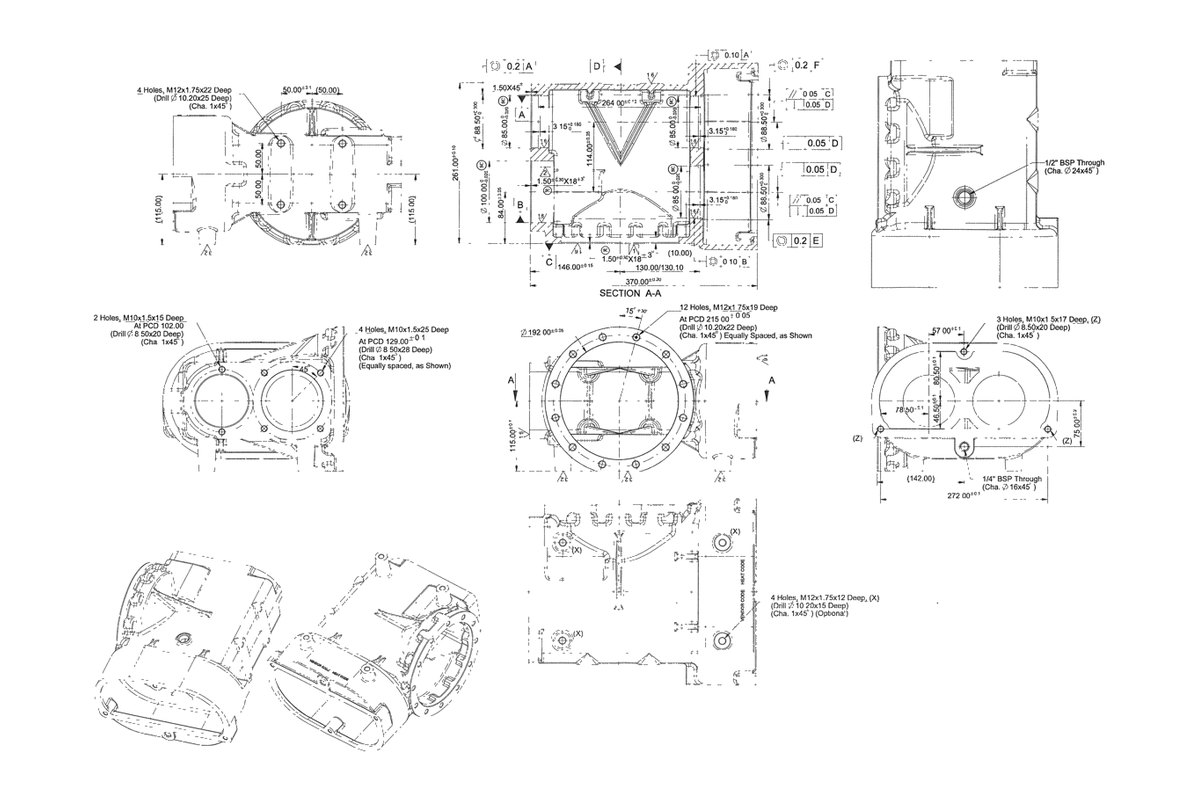
2D Drawing to 3D Model Conversion
Legacy 2D drawings converted into fully-featured parametric 3D models — with the ambiguities in the original drawings resolved rather than guessed at.
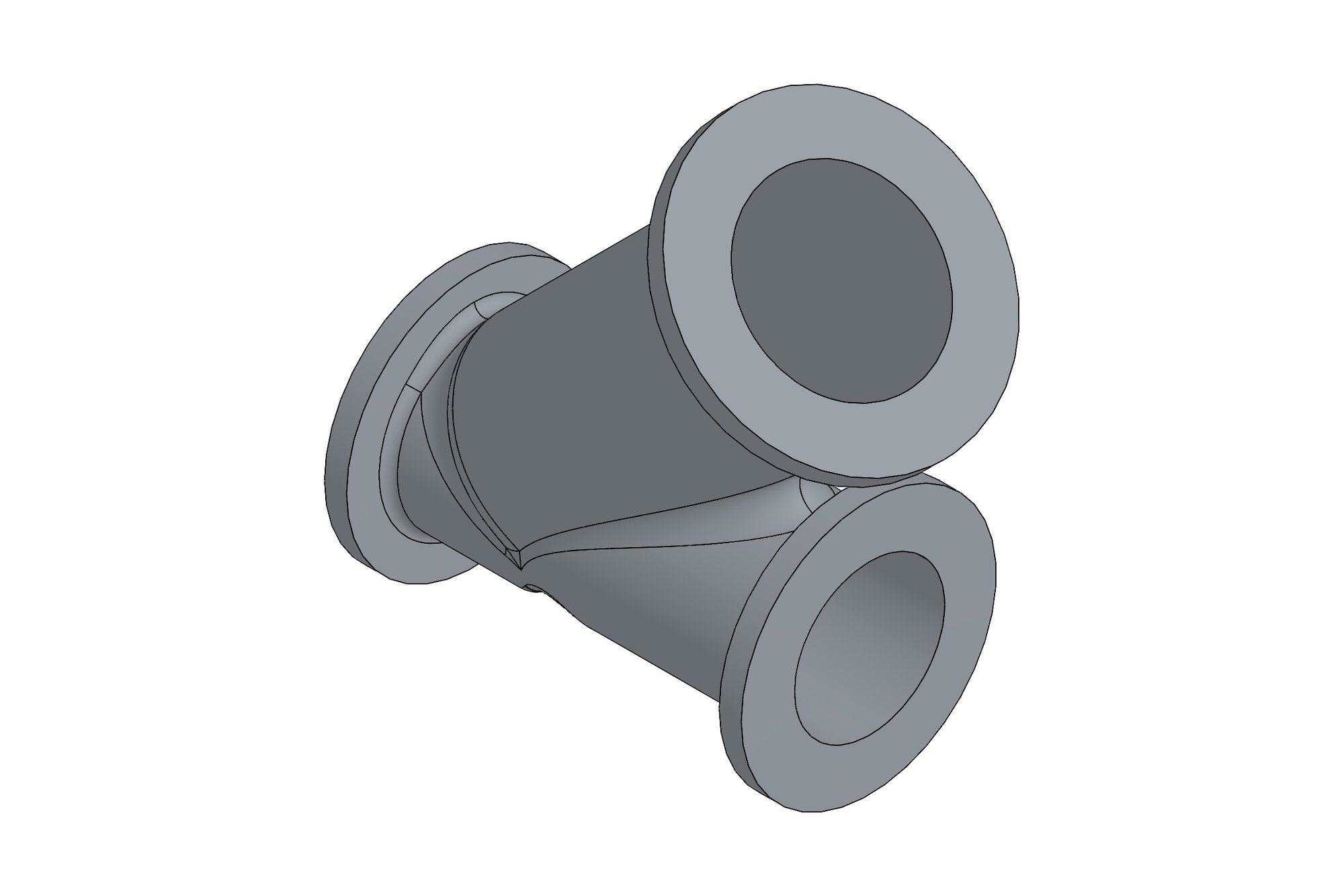
DN250 Class 150 Bellow-Seal Globe Valve: 2D to 3D
Body, bonnet, plug and stem of a 250 NB class 150 Y-type bellow-seal globe valve modelled in SolidWorks from the valve maker's 2D drawings, with flange drilling to the standard, machining allowances and a mated assembly for the maker's catalogue and manufacturing.
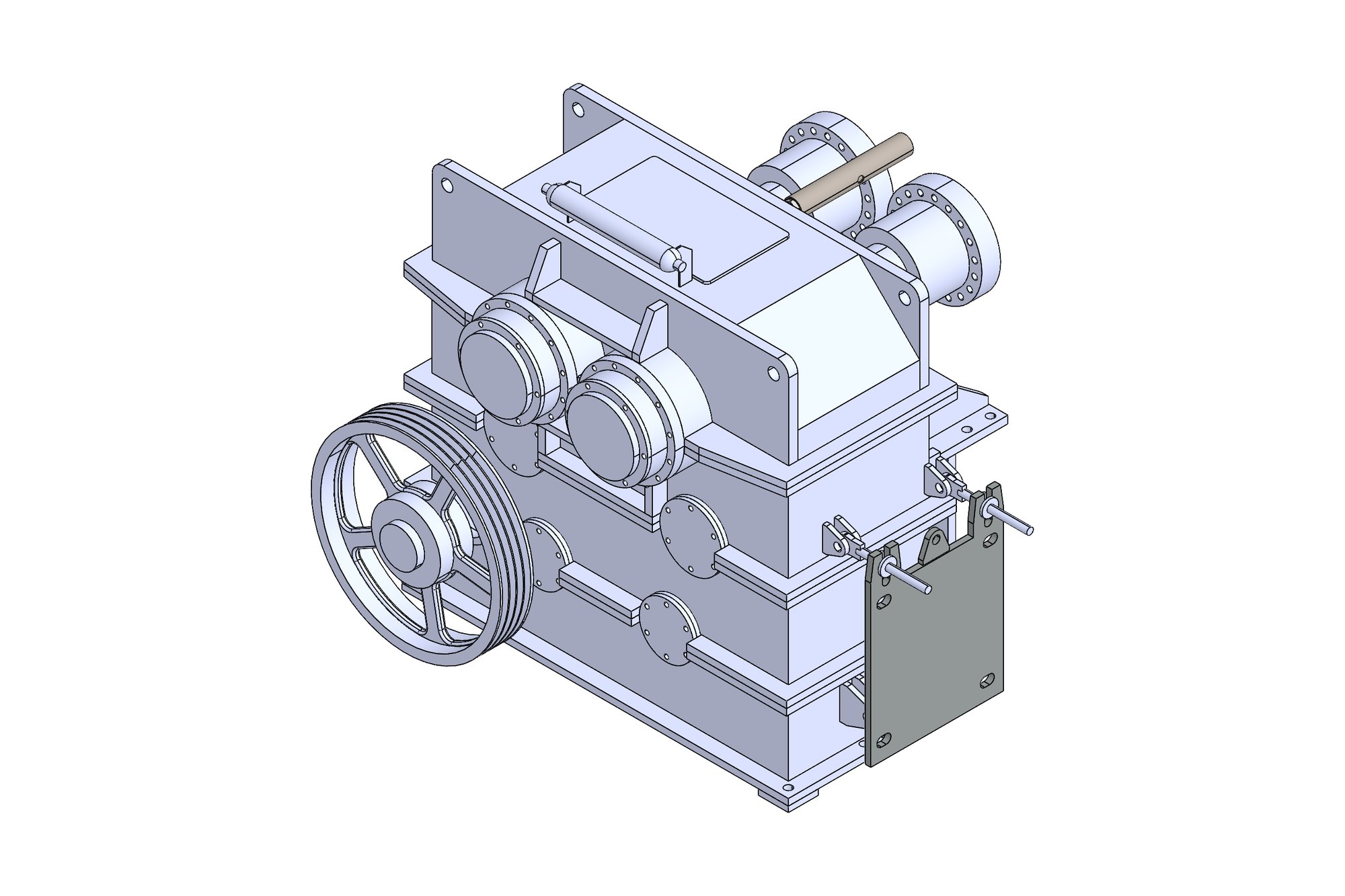
Press Drive Gearbox with Flywheel Input
A twin-output press drive gearbox with a flywheel on the input shaft, rebuilt in 3D from the manufacturer's 2D assembly drawing and parts list — housing, gear shafts, bearings, covers and flywheel — so it could be reissued as a complete machining and assembly package.
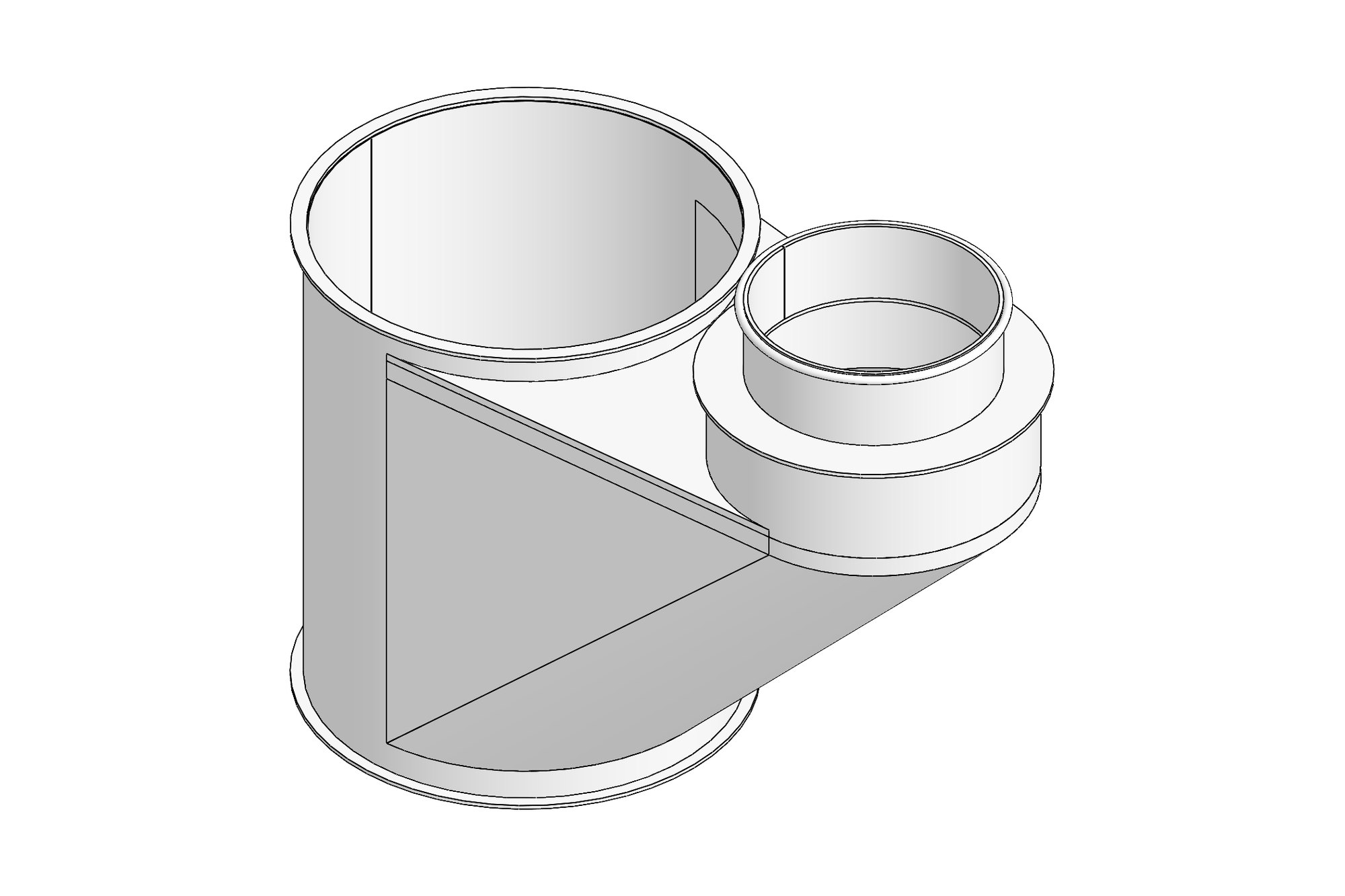
Sheet-Metal Ductwork Package from a European Customer's Drawings
Two dust-extraction ductwork assemblies — cyclone body, transition and hopper cone — modelled in SolidWorks from a European customer's French-language 2D drawings, then issued as 21 part drawings with flat patterns and thickness-sorted DXF files for a Gujarat sheet-metal shop.
Commercials
Three ways to engage
No price lists — every package is quoted on its inputs — but the model is always one of these.
Fixed-price project
Defined scope, itemised quote, agreed delivery date. Best for drawing packages, conversions, reverse engineering and analysis studies with clear inputs.
Hourly with a cap
For design development where scope evolves. Weekly hours against an agreed cap; nothing exceeded without approval.
Dedicated engineer
A named engineer on your work month by month, inside your CAD, PDM and standards — an extension of your drawing office.
NDA before files
Your NDA or ours, signed before any drawing changes hands. IP transfers to you on payment.
Controlled access
Only the engineers on your job see your files; stored on controlled systems, deleted on request.
Second-engineer check
Every package checked against your inputs and standard by an engineer who did not do the work.
Technical FAQ
Questions engineers ask before outsourcing cad conversion
Do you trace the 2D geometry or rebuild it properly?
We rebuild it. An engineer reads the orthographic views, models the part as features (extrudes, holes, fillets, patterns) and regenerates drawings from the model. Traced or auto-converted geometry is not editable and is not what we deliver.
How do you handle a PDF drawing that is not to scale or has conflicting dimensions?
We scale-check against known dimensions first. Conflicts are listed in a query sheet with our recommended resolution and agreed with you before modelling; the resolution is recorded in the check record.
Can you migrate our whole library from one CAD system to another?
Yes. We audit the library, agree naming and property mapping, convert a sample batch for approval and then run the rest in priority order, delivering folder structures ready for your PDM.
Will STEP files from a supplier become editable models?
Yes. We rebuild the geometry as a native parametric model with a feature tree rather than importing a dumb solid, so your team can change it later.
What verification do we get?
A per-file check record comparing dimensions, features and mass properties to the source, plus an exception list for ambiguities and how they were resolved.
Which CAD versions can you deliver?
Current and older versions of SolidWorks, Inventor, Creo, Solid Edge, NX and AutoCAD. Tell us the exact version your team runs.
How is conversion priced?
Per file or per batch, as a fixed quote after we see a sample of the archive; send a few typical drawings and you get the quote within one business day. Large libraries are quoted per batch so you control the pace and budget.
How long does CAD conversion take?
It depends on the number of drawings, their condition and how complex the parts are, so we do not publish fixed durations. The quote you receive within one business day states the delivery date for the sample and each batch, and large libraries are delivered batch by batch so your team can start using files early.
How can we tell the converted model is fully featured and not a dumb solid?
Open the sample. Every part should have a readable feature tree (sketches, extrudes, holes, patterns and fillets) that changes cleanly when you edit a dimension, and the drawings should be generated from the model. The per-file check record lists dimensions and mass properties against the source, so you can audit any file without re-measuring it.
Do we need to convert every legacy 2D drawing to 3D?
Usually not. Parts that are still manufactured, revised or used in current assemblies benefit most from 3D. Obsolete or rarely used drawings can stay as clean 2D DWG or indexed PDF. We help you sort the archive into those groups during the audit, so you only pay to convert what you will use.
Which file formats do you deliver?
Native SolidWorks, Inventor, Creo, Solid Edge, NX or AutoCAD parts, assemblies and drawings in the version you run, plus DWG and DXF for 2D, STEP (AP214 or AP242), IGES or Parasolid for exchange, and PDF prints of every drawing.
Related services
Send the job. Get an engineer's answer.
Drawings, a sketch or a description — itemised quote, deliverables list and timeline within one business day (IST).