- Client
- Sheet-metal fabricator supplying a European OEM, Gujarat (name withheld under NDA)
- Industry
- Sheet Metal & Steel Fabrication
- Service
- CAD Conversion & Migration
- Platform
- SolidWorks
- Client region
- India
- Input
- Customer 2D drawings (French), SPFT001 steel / SPFT002 stainless, js13 general tolerance
- Output
- 2 assemblies · 20 sheet-metal parts · 21 drawings · DXF per thickness (1.5, 2, 4 mm)
- Parts
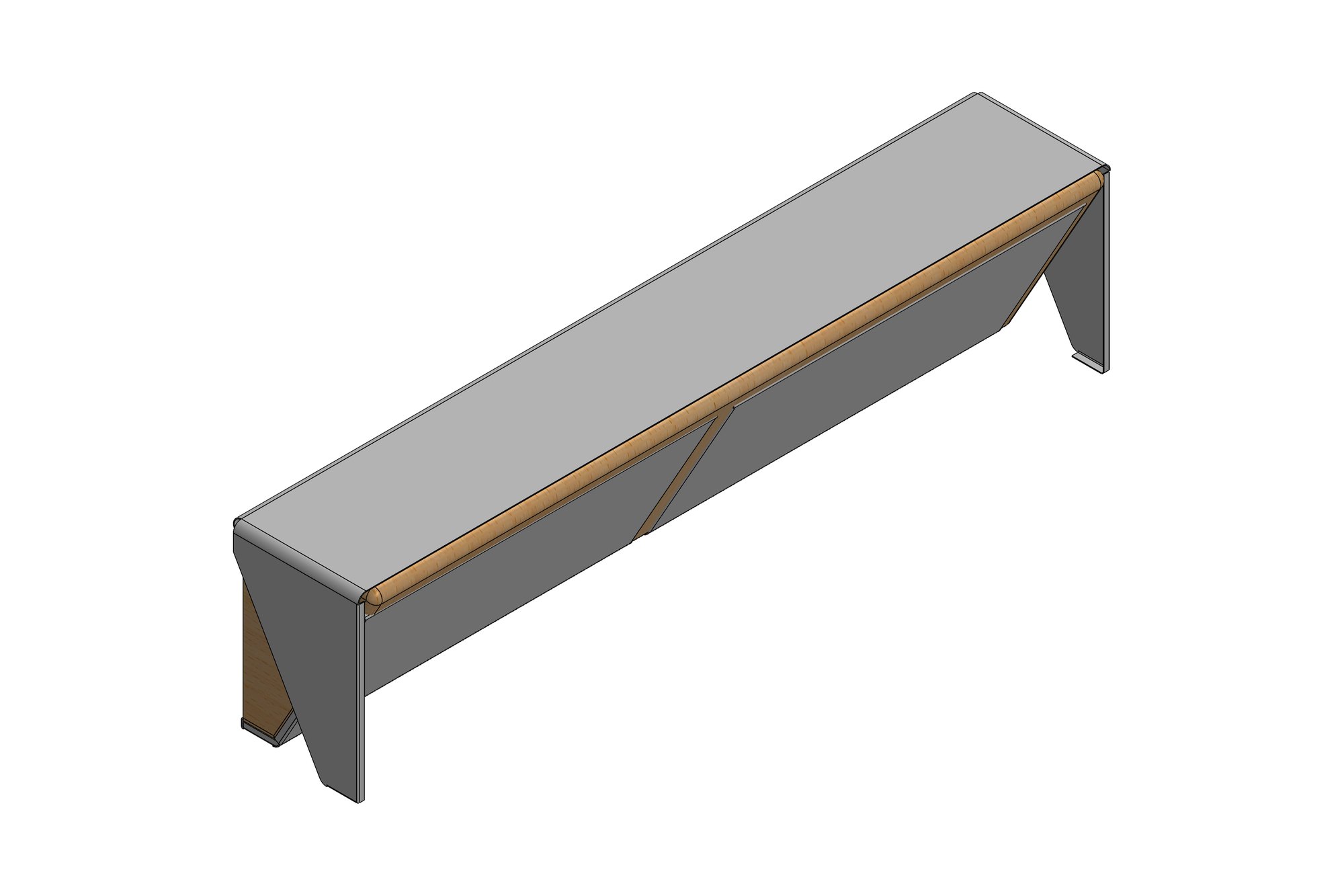
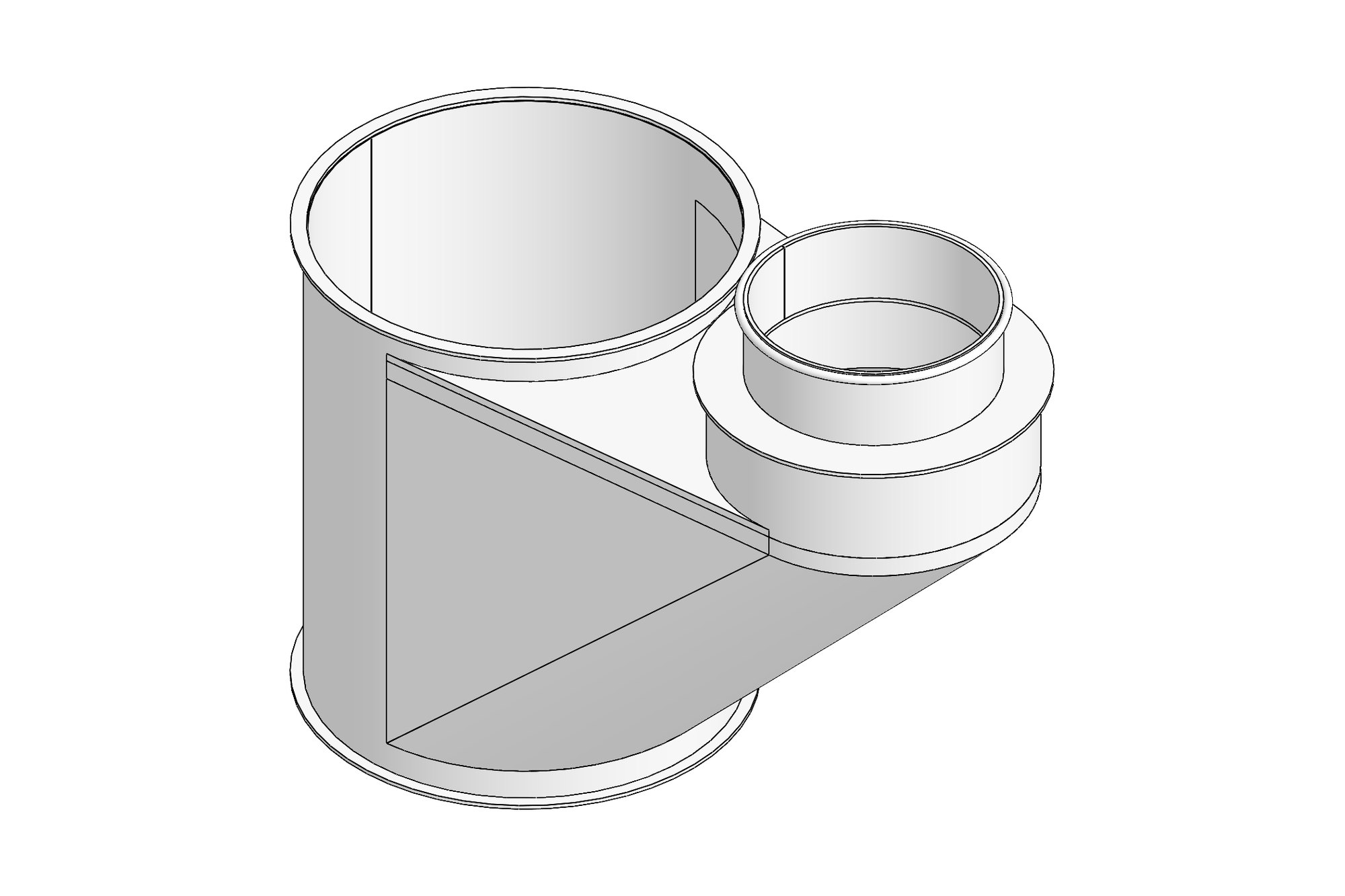
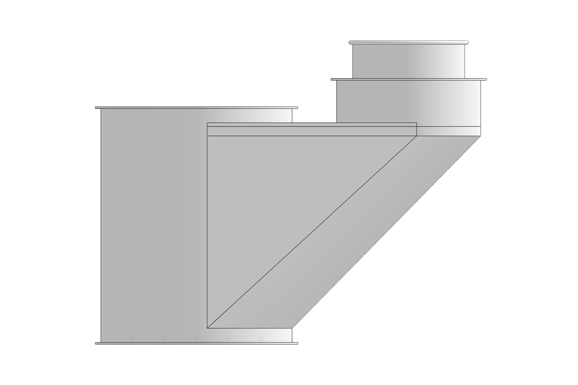
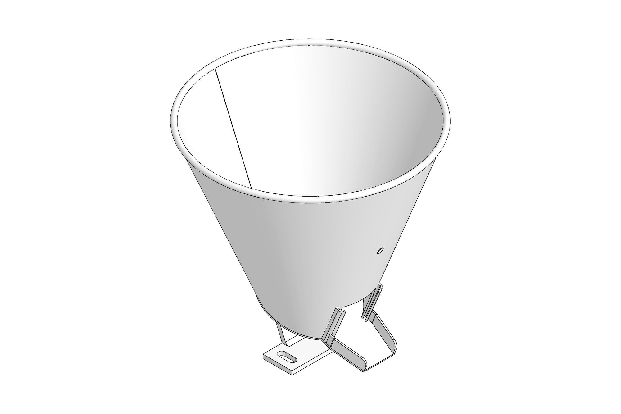
- Cyclone body, inlet transition, hopper cone, flanges and stiffeners
The challenge
The customer's drawings were correct but written for their own shop: general notes in French referring to internal fabrication specifications, finish codes "F" and "V" defined in a separate document, and a js13 general tolerance that the fabricator had to interpret correctly on every unstated dimension. Several parts were drawn as finished folded shapes with no flat pattern.
The order was for two assemblies with around twenty sheet-metal parts in three thicknesses, and the fabricator needed to nest each thickness separately. That meant every part had to be a true sheet-metal model with the right bend radius and K-factor for the material, not a solid that looked right.
Our approach
Each part was rebuilt as a SolidWorks sheet-metal part from the customer's dimensions, with the bend radius and K-factor set per thickness and the flat pattern checked against any overall dimensions the customer gave. The cyclone body's 628 mm rolled shell, the rectangular-to-round transition and the hopper cone were all produced as developable sheet-metal features so their flat patterns are exact.
Where the French notes referred to the customer's specifications, we translated the requirement onto our drawing as an explicit instruction — material grade, finish, "break sharp edges" — so the shop floor did not have to read the original. A query sheet listing the unresolved points was returned to the customer before modelling was closed.
The output package follows the fabricator's own title block and critical-parameter marking: a drawing per part with the flat pattern and bend lines, a DXF of the flat pattern named with its thickness (for example "-01_2MM.DXF"), and an assembly drawing with the customer's part numbers so their inspection could trace every item back to the order.
What was delivered
Forty PDF drawings and twenty DXF flat patterns, sorted by thickness, delivered against the two customer assemblies. The fabricator cut, folded and shipped the first batch without a single drawing query from the customer.
- SolidWorks sheet-metal models for 2 assemblies (20 parts)
- 21 part and assembly drawings with flat patterns
- DXF flat patterns named by thickness for nesting
- Translated manufacturing notes on each drawing
- Query sheet returned to the customer before release
Standards and conventions applied
- ISO 2768 / js13 general tolerances as specified by the customer
- Sheet-metal bend tables per thickness (1.5, 2, 4 mm)
- Fabricator title block and critical-parameter marking
Have a similar requirement? Send the drawings, a sketch or a description — an engineer will scope it and reply with an itemised quote within one business day. Request an engineering quote.