
Manufacturing Support
Sheet Metal Design & Fabrication Drawing Services
Sheet metal parts, weldments and fabricated assemblies designed and detailed for the shop that will make them — flat patterns and DXFs that match your press brake, weld symbols to AWS or ISO, cut lists, hardware callouts and BOM-complete fabrication drawing packages. Delivered native in your CAD, to your standard.
Service Overview
Drawings A Fabricator Can Build From Without A Phone Call
Fabrication drawings fail in predictable ways: flat patterns that do not match the bend allowance of the real press brake, weld symbols that leave the welder guessing, hardware with no PEM or rivet-nut specification, and assembly drawings with no sequence. We detail for the shop floor — the laser programmer, the brake operator, the welder and the fitter — and we ask for your bend tables, hardware preferences and welding process before the first part is unfolded.
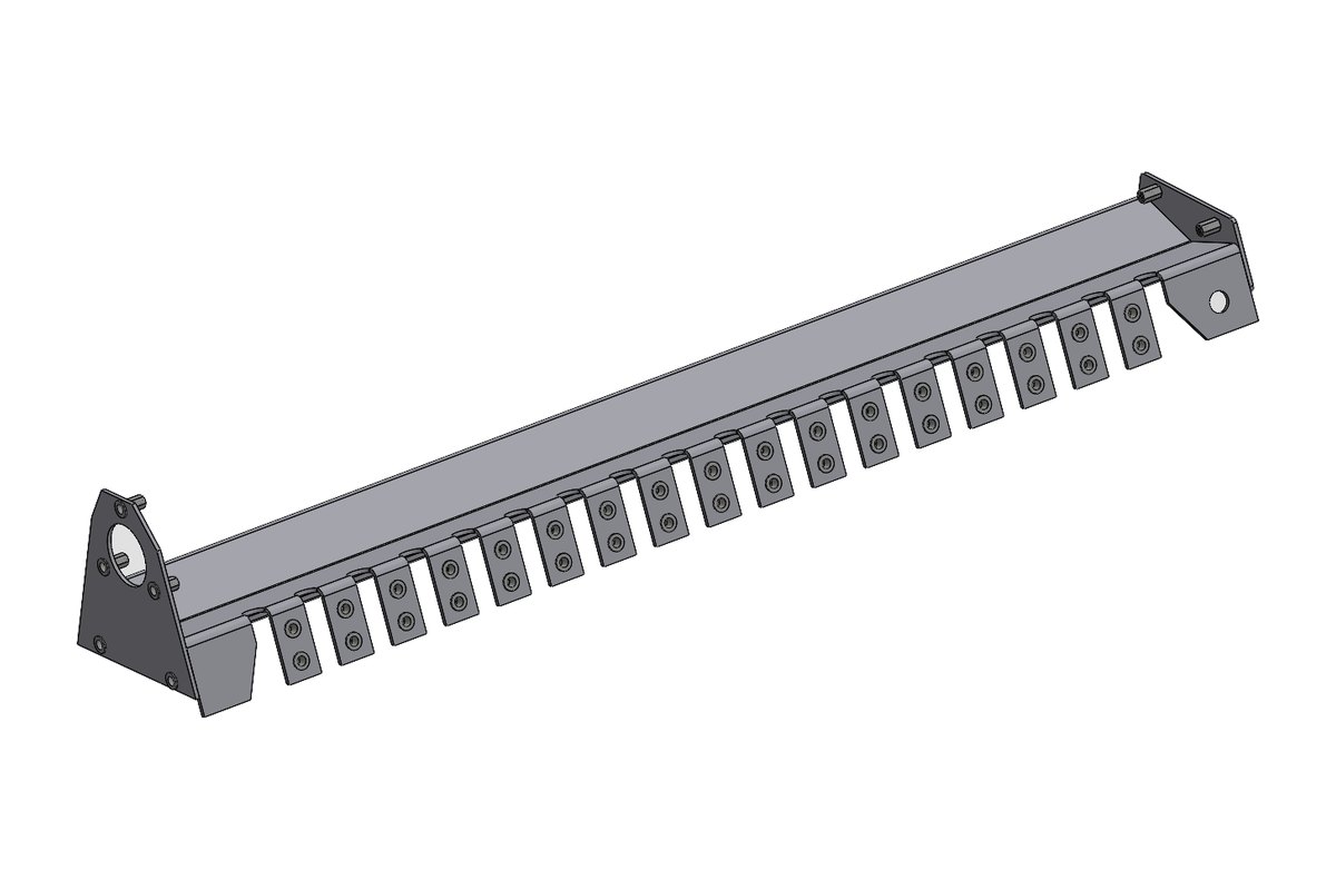
The same team designs the parts, so when a flange will not clear a bend or a weld is unreachable, it is fixed in the model rather than discovered on the floor. Our fabrication work includes gearbox housings, machine frames, guards, enclosures and structural guides, each delivered as a complete package.
- Sheet metal part design with flat patterns, bend tables or K-factors you specify
- Weldment and frame design with structural profiles, cut lists and weld callouts
- Fabrication drawing packages: part, weldment, sub-assembly and GA drawings with BOMs
- DXF/DWG for laser, plasma, waterjet and punch, with or without bend lines, etch and bend marks
- Hardware integration: PEM, rivet nuts, inserts, hinges, latches and gaskets
- Enclosures, guards, chutes, hoppers, cabinets, brackets and machine frames
What this service is not: We do not provide CNC nesting or press-brake programming files beyond DXFs; those stay with your shop's software and operators.
What's Included
Sheet Metal & Fabrication Capabilities
Sheet Metal Part Design
Bends, reliefs, hems, louvres, embosses and formed features designed to your material, thickness, tooling and minimum flange rules.
Flat Patterns & DXFs
Unfolded to your bend table or K-factor; DXF exported with bend lines, etch marks and part numbers as your laser programmer needs.
Weldments & Frames
Structural profiles, gussets and plates with cut lists, weld symbols and sequence notes for frames, skids and bases.
Fabrication Drawing Packages
Part, weldment and GA drawings with BOMs, balloons, hardware callouts and finish specifications.
Enclosures & Guards
Electrical and equipment enclosures, machine guards and cabinets with doors, hinges, latches, gaskets and ventilation.
DFM For Fabrication
Review of existing designs for bend feasibility, weld access, tolerance stack-up across bends and cost drivers.
What We Need From You
Inputs We Work From
Send whatever you have. We list anything missing or ambiguous in a query sheet and agree it with you before modelling starts — nothing is assumed silently.
- Sketches, concept models, existing drawings or a sample part
- Material, thickness and finish; your bend table, K-factor or press-brake tooling data
- Welding process and your preferred weld symbol standard (AWS A2.4 or ISO 2553)
- Hardware preferences: PEM, rivet-nut, hinge and latch catalogues
- Drawing template, title block and DXF conventions (layers for cut, bend, etch)
- Target CAD platform and version
What You Receive
Deliverables & File Formats
Models
- Native sheet metal and weldment models (SolidWorks, Inventor, Creo, Solid Edge, NX)
- Configurations for material and thickness variants
- STEP/Parasolid for suppliers on other platforms
Shop files
- Flat-pattern DXF/DWG per part, bend lines and etch on your layers
- Cut lists for profiles and plates; bend tables on drawings
- Weldment drawings with weld symbols, sizes and sequence notes
Package
- Fabrication drawing set: part, weldment, sub-assembly and GA with BOMs
- Hardware and finish callouts; mass and paint-area where needed
- Check record against inputs and standards
Native files in your platform and version (older versions on request), plus neutral STEP AP214/AP242, IGES, Parasolid, DXF and PDF as needed.
Standards & Platforms
Drawn To Your Standard, Delivered In Your CAD
We work to the drawing and design standards your market specifies. Editions below are current as of October 2026.
Standards we apply
- AWS A2.4:2020 — Weld symbols for North American fabrication drawings
- ISO 2553:2019 — Weld symbols for ISO-market (EU, UK, Australia, India) drawings
- ASME Y14.5-2018 (R2024) / ISO GPS — Tolerancing, including tolerance stack-ups across bends
- BS 8888:2025 / AS 1100 — Drawing presentation for UK and Australian fabricators
- AS/NZS 5131:2016 (Amd 1:2020) — Fabrication and erection documentation conventions for Australian structural work
- Your bend tables and DXF layer standard — Applied so flat patterns and cut files match your shop without rework
Native CAD platforms
You receive editable native files, not just exports. We do not advertise platforms we cannot deliver natively.
How The Work Runs
Our Process For This Service
Shop data first
We collect your material, bend and hardware rules so the model matches your process from the start.
Design and unfold
Parts and weldments are modelled, unfolded to your bend data and checked for bend feasibility and weld access.
Detail and DXF
Fabrication drawings, cut lists and DXFs are produced on your template and layer standard.
Check and deliver
A second engineer checks flat patterns, symbols and BOMs against the inputs; files delivered native plus DXF/PDF.
Worked Example
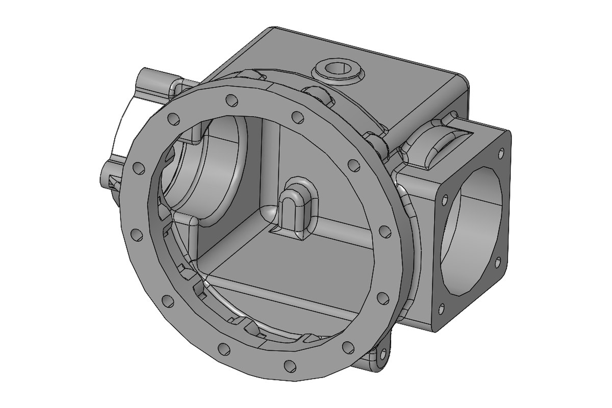
Fabricated Gearbox Housing Design
A fabricated gearbox housing designed as a weldment with sheet and plate parts — flat patterns to the client's bend data, weld symbols, machining allowances for bearing bores after welding, and a fabrication drawing package with cut list and BOM in SolidWorks and AutoCAD.
- Industry: Power Transmission
- Software: SolidWorks, AutoCAD
Engagement Models
Three Ways To Work With Us
Every quote states scope, deliverables, formats, standard, revision rounds and deadline. Prices are quoted per project — in USD, EUR, GBP, AUD or INR.
Fixed price per job
Best for defined scopes — a drawing set, a conversion batch, one analysis. You know the total before work starts.
Hourly with a cap
For evolving design work where scope is still forming. Hours are logged, reported weekly and never exceed the agreed cap without your sign-off.
Dedicated engineer
A named engineer reserved for your work, month by month, on your templates and in your CAD — an extension of your own design office.
Confidentiality & IP
Your Designs Stay Yours
NDA before files
We sign your NDA, or send ours, before a single drawing is shared.
IP assigned to you
Models, drawings and calculations are your property on payment. We keep no rights.
Named engineer
Only the engineers on your job can open your files. You deal with them directly.
Deleted on request
Project data is removed from our systems when you ask, with written confirmation.
Technical FAQ
Questions Engineers Ask Us
Which K-factor or bend allowance do you use?
How are DXFs delivered for the laser?
Do you use AWS or ISO weld symbols?
Can you detail a frame for welding and then machining?
Do you design enclosures to an ingress rating?
Can you review an existing design for fabrication cost?
Do you also do structural steel detailing?
Explore More
Related Services & Industries
Mechanical 3D Modelling & 2D Drafting
Parametric models, manufacturing and GA drawings, GD&T, BOMs.
Learn moreMachine & Equipment Design
Special-purpose machines, conveyors, fixtures, gearboxes and drives.
Learn moreSend Us The Job — We'll Scope It Honestly
Drawings, a sketch, a scan or just a description. You get an itemised quote and a timeline, usually within one business day, under NDA if you prefer.