
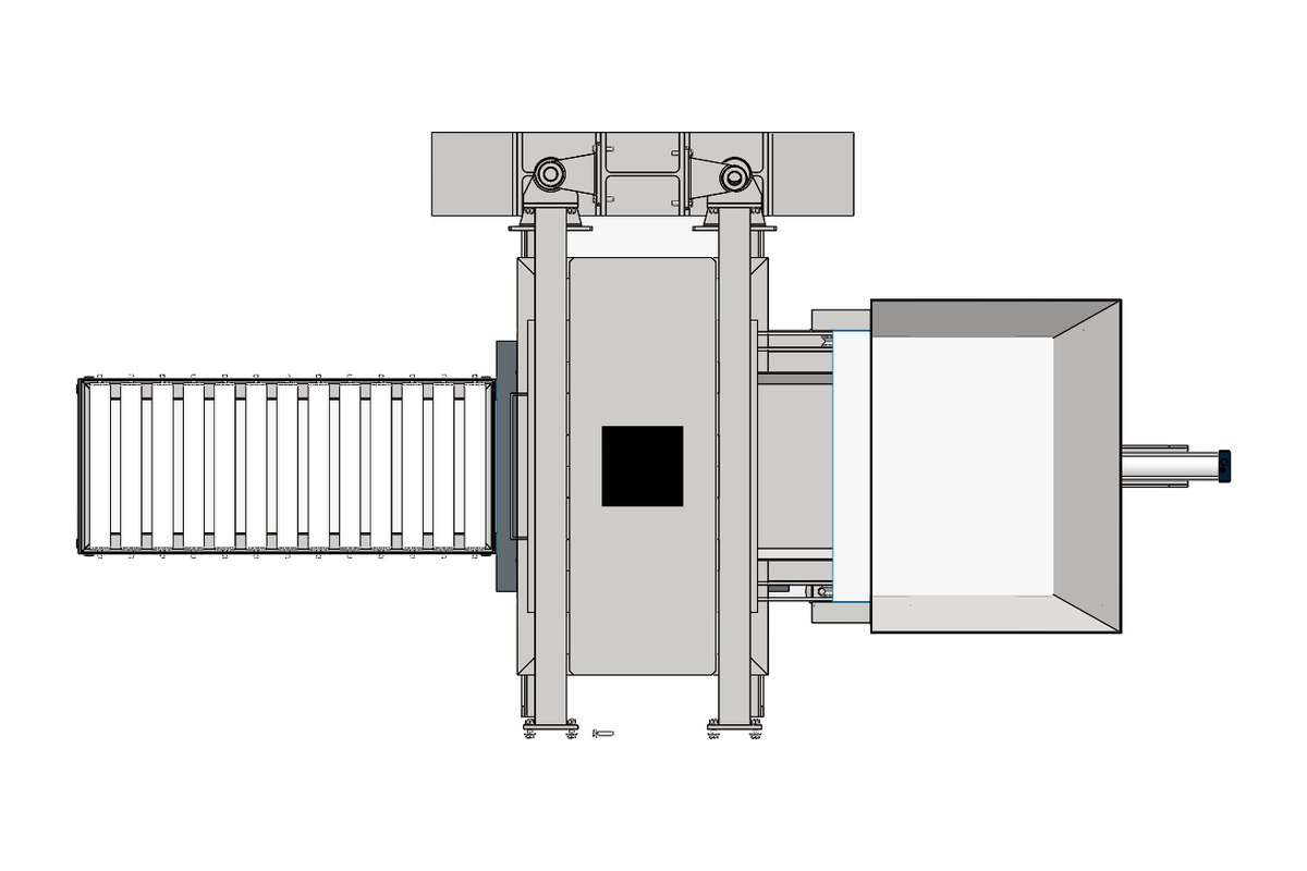
CAD Conversion
2D to 3D CAD Conversion: A Practical Workflow Guide
Converting legacy 2D drawings into fully-featured 3D models is one of the most requested — and most misunderstood — CAD services. Here's how a clean conversion actually works.
CAD Conversion2 February 2026·By The Sarjan Solution Team
Converting legacy 2D drawings into fully-featured 3D models is one of the most requested — and most misunderstood — CAD services. Done well, it produces a parametric model your team can actually edit. Done poorly, it produces a "dumb" solid that looks right but breaks the moment someone tries to change a dimension. Here's how a clean conversion actually works.
Step 1: Audit The Source Drawings
Before any modelling starts, the drawing set gets reviewed for completeness — missing views, ambiguous dimensions, and tolerance notes that don't match the part's evident function. Flagging these upfront avoids rework later and often surfaces questions worth asking the client directly.
Step 2: Rebuild Features, Not Just Geometry
The difference between a good conversion and a bad one comes down to feature intent. A hole isn't just a cylinder cut from a solid — it's a hole feature with a diameter that can be edited, a pattern if it repeats, and a relationship to the faces around it. Modelling with proper feature history (extrudes, revolves, patterns, fillets — in the order a machinist would actually think about the part) is what makes the resulting 3D model maintainable.
Step 3: Apply Real-World Design Intent
Where a drawing implies symmetry, a standard fastener size, or a common wall thickness across a sheet-metal part, the model should capture that relationship — not just replicate the numbers as isolated dimensions. This is what lets someone change one parameter later and have the model update sensibly, instead of breaking.
Step 4: Build The Assembly Relationships, Not Just The Parts
For assemblies, individual part conversion is only half the job. Mates and constraints need to be rebuilt natively in the target CAD platform so the assembly behaves correctly — components move where they should, interference checks are meaningful, and exploded views and BOMs generate automatically.
Step 5: Validate Against The Original Drawing
The finished 3D model gets checked back against the original 2D drawing dimension by dimension, and against any known physical part if one is available. This catches transcription errors before they reach your shop floor.
When 2D-to-3D Conversion Makes Sense
This service pays off fastest when a company standardises on 3D-first design, needs to run simulation or CNC programming from a model that only exists as a drawing, or is digitising an archive of legacy parts before the paper originals degrade further. If that sounds like where you are, it's worth a conversation about scope and timeline.
SS
Written by the Sarjan Solution Team
CAD design & engineering consultancy, Ahmedabad & Gandhinagar — delivering CAD, simulation and product design services since 2018.
Keep Reading
More Insights
Ready To Engineer Your Next Product?
Send us your requirement with a brief description and we'll reach out with the best quote — usually within one business day.