
CAD Conversion
How to Convert PDF Drawings to CAD: Methods, Accuracy and What It Really Takes
Many companies hold drawings only as PDFs. Turning them into editable DWG files or 3D models is easy to start and easy to get wrong. Here is how it actually works.
CAD Conversion3 October 2026·By The Sarjan Solution Team
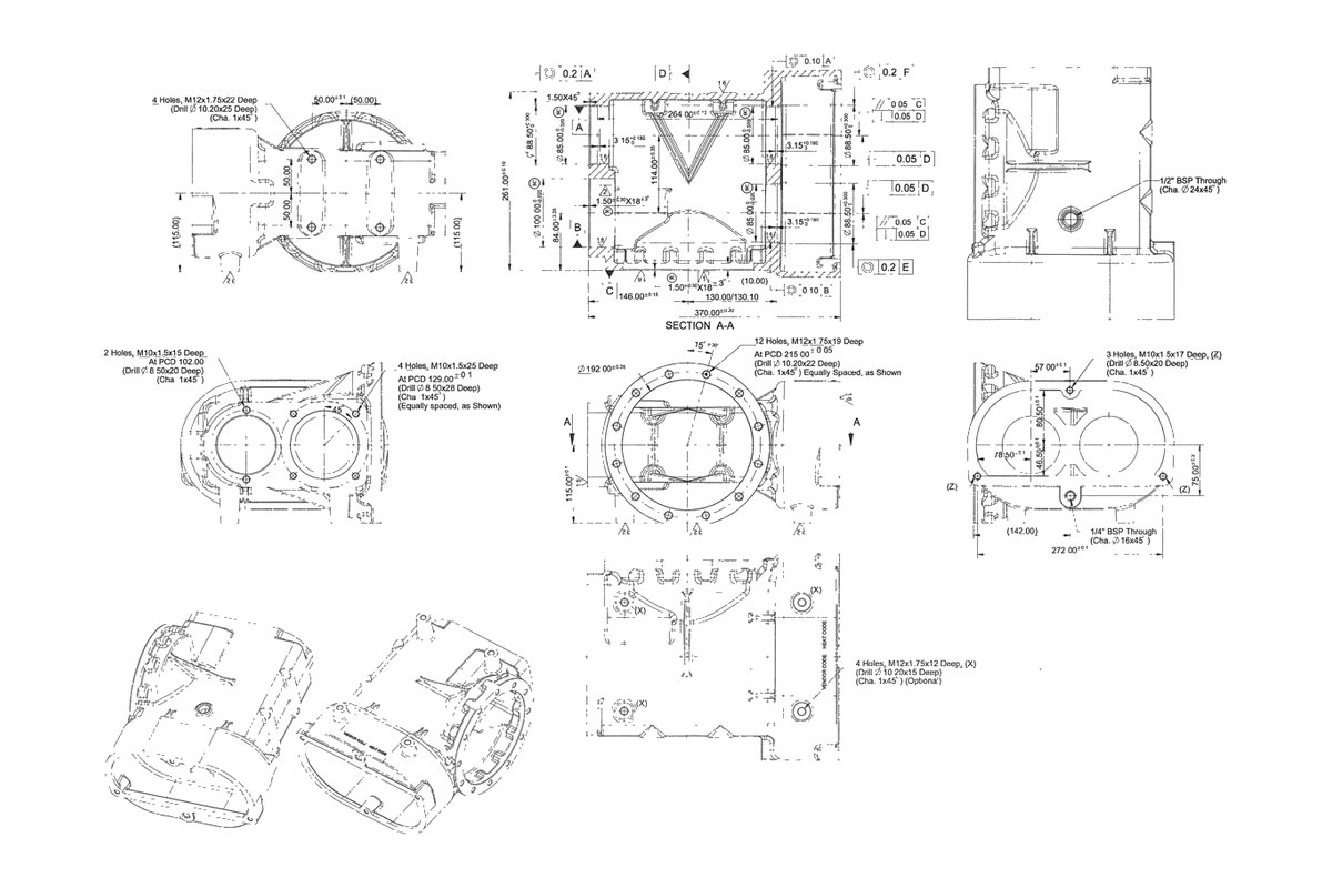
Almost every manufacturer has drawings that exist only as PDFs: drawings from a supplier who has closed, scans of old paper prints, or exports from a CAD system nobody uses any more. Sooner or later someone needs to change one, and a PDF cannot be edited the way a CAD file can. This guide explains the options for converting PDF drawings to CAD, what each one is good for, and where each goes wrong.
First, find out which kind of PDF you have
Not all PDFs are the same, and the type decides which conversion method is possible.
- Vector PDF. Exported directly from a CAD program. Lines, arcs and text are stored as geometry. Zoom right in and the lines stay sharp, and you can usually select the text. This is the best starting point.
- Raster (scanned) PDF. A photograph of a drawing, made of pixels. Zoom in and the lines go blurry or blocky, and the text cannot be selected. Most old paper drawings are in this form.
- Mixed PDF. A vector drawing with scanned stamps, mark-ups or signatures pasted on top. Common on revised drawings.
Method 1: Automatic import (vector PDFs only)
Modern CAD programs can import vector PDFs — AutoCAD, for example, has a PDF import command. The geometry comes in as lines, arcs and text in seconds. It looks finished, but it rarely is:
- Scale is often wrong. The PDF was printed to a sheet size, so the imported geometry is in "paper" units, not real dimensions. Every line has to be scaled — and if the drawing was not to scale in the first place, no single factor will fix it.
- Geometry is broken up. Circles arrive as many short segments, lines as disconnected pieces, and hatching as hundreds of separate lines.
- Dimensions are dead. Dimension text arrives as plain text, not as associative dimensions. Change the geometry and the numbers stay the same.
- Drawn geometry and dimension values disagree. On many older drawings, the draftsperson changed a dimension value without redrawing the line. An automatic import copies the line, not the intended size.
Automatic import is useful as a reference layer to trace over. On its own it does not produce a drawing you can trust for manufacturing.
Method 2: Raster-to-vector software (scanned PDFs)
Raster-to-vector programs try to trace the pixels of a scan into lines and arcs. On clean, high-resolution scans of simple drawings they give a rough start. On real-world scans — folded paper, coffee stains, faded pencil, skewed scanning — they produce a mess of fragments that takes longer to clean up than redrawing. Text and dimensions are especially unreliable.
Method 3: Redraw from dimensions (the reliable method)
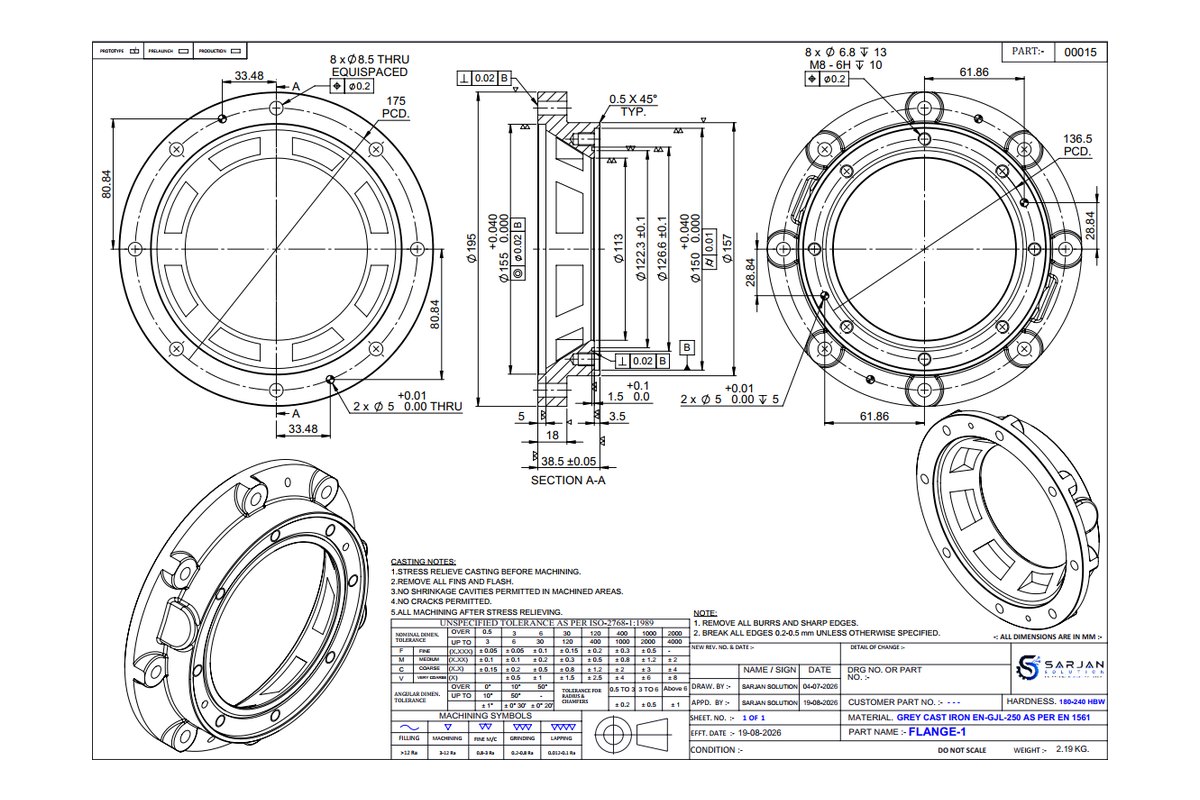
The method professional conversion uses is to redraw the part from its dimension values, using the PDF only as a reference. The engineer reads each dimension, builds correct geometry at true size, and recreates the dimensions as real, associative CAD dimensions. Done properly, this:
- produces geometry that is exactly to size, regardless of how the PDF was scaled
- finds conflicts — dimensions that do not add up, missing sizes, views that disagree — and lists them for you to resolve
- applies your layer standard, title block and drawing standard (ASME or ISO)
- gives you a file you can edit with confidence
2D DWG or 3D model?
Decide what you need the result for before converting:
- 2D DWG/DXF is enough if you only need to revise the drawing, send DXFs to a laser cutter, or archive the design in an editable form.
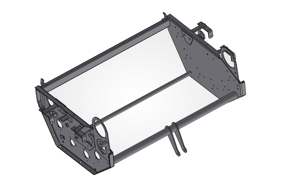
- A 3D parametric model (SolidWorks, Inventor, Creo and so on) is worth it if the part will be modified, checked for interference in an assembly, analysed with FEA, or made by CNC. The 3D model is built from the PDF dimensions, and new 2D drawings are then generated from it — so the views always agree.
Our 2D to 3D conversion checklist covers that step in more detail.
What affects the effort (and the quote)
- Legibility: a clean vector PDF is faster than a faded scan where every number has to be checked.
- Complexity: number of views, sections, details and features per sheet.
- Completeness: missing or conflicting dimensions mean questions before work can finish.
- Output: 2D only, 3D only, or 3D plus new drawings; neutral formats (STEP, DXF) in addition to native files.
- Standards: keeping the original layout, or bringing drawings up to a current ASME or ISO standard.
- Volume: a batch of similar drawings is faster per sheet than single, unrelated ones.
How to prepare your PDFs
- Send the best copy you have. Scan paper at 300–600 dpi, flat and straight, in greyscale.
- Include every sheet of a drawing set, plus the parts list if there is one.
- Say which file wins if a PDF disagrees with a physical part or a newer revision.
- State the output: 2D or 3D, CAD software and version, drawing standard and units.
- Send one finished drawing in your current template, if you have one.
When a PDF is not enough
Sometimes the PDF is too poor or too incomplete to rely on, or the part has been changed on the shop floor since the drawing was made. Then the reliable route is to measure or 3D-scan the physical part — see our reverse engineering service.
We convert PDF, scanned and paper drawings to DWG and to 3D models for clients in the UK, USA, Germany, Australia and worldwide. See our CAD conversion service.
Frequently asked questions
Can a PDF be converted to an editable CAD file?
Yes. Vector PDFs can be imported into CAD directly as a starting point, but for an accurate, editable drawing the geometry should be redrawn to the dimension values. Scanned PDFs always need redrawing.
Is automatic PDF to DWG conversion accurate?
Rarely enough for manufacturing. Imported geometry is often at the wrong scale, broken into fragments, and its dimensions are plain text. It is useful as a reference to trace over, not as a final drawing.
Can you make a 3D model from a PDF drawing?
Yes. A 3D parametric model is built from the dimensions on the PDF views, and fresh 2D drawings can then be generated from the model.
What scan resolution is needed for PDF to CAD conversion?
Scan paper drawings at 300 to 600 dpi in greyscale, flat and straight. Higher resolution helps most where dimension text is small or faded.
SS
Written by the Sarjan Solution Team
CAD design & engineering consultancy, Ahmedabad & Gandhinagar — delivering CAD, simulation and product design services to manufacturers in India, the UK, Europe and the USA since 2018.
Keep Reading
More Insights
Send Us Your PDFs For A Fixed Quote
Send us your requirement with a brief description and we'll reach out with a fixed quote in GBP, USD, EUR or INR — usually within one business day.