- Client
- Extruder gearbox manufacturer, Ahmedabad (name withheld under NDA)
- Industry
- Gearboxes & Power Transmission
- Service
- CAD Conversion & Migration
- Platform
- Solid Edge, AutoCAD
- Client region
- India
- Input
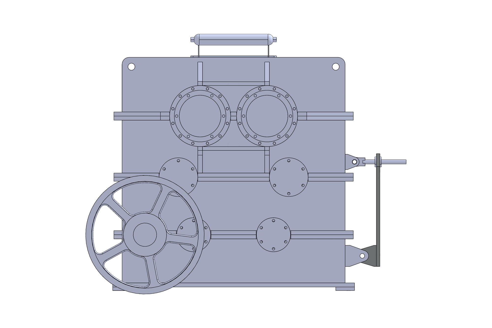
- Spoked flywheel on the input shaft, belt-driven
- Outputs
- Twin output shafts through bolted bearing covers
- Input data
- 2D assembly drawing P15-09 with parts list
The challenge
The only record of the gearbox was a single 2D sheet — assembly drawing, details and a parts list — drawn years earlier. Fits, keyways and bearing seats were specified in the notes rather than on views, and the housing had never been modelled, so every new order meant re-reading the sheet and hoping nothing had changed.
A press drive also has features a normal reducer does not: the flywheel has to be balanced and keyed, the shafts take reversing shock loads, and the twin outputs must be timed to each other through the gear train. All of that had to be captured in the model, not just the outline.
Our approach
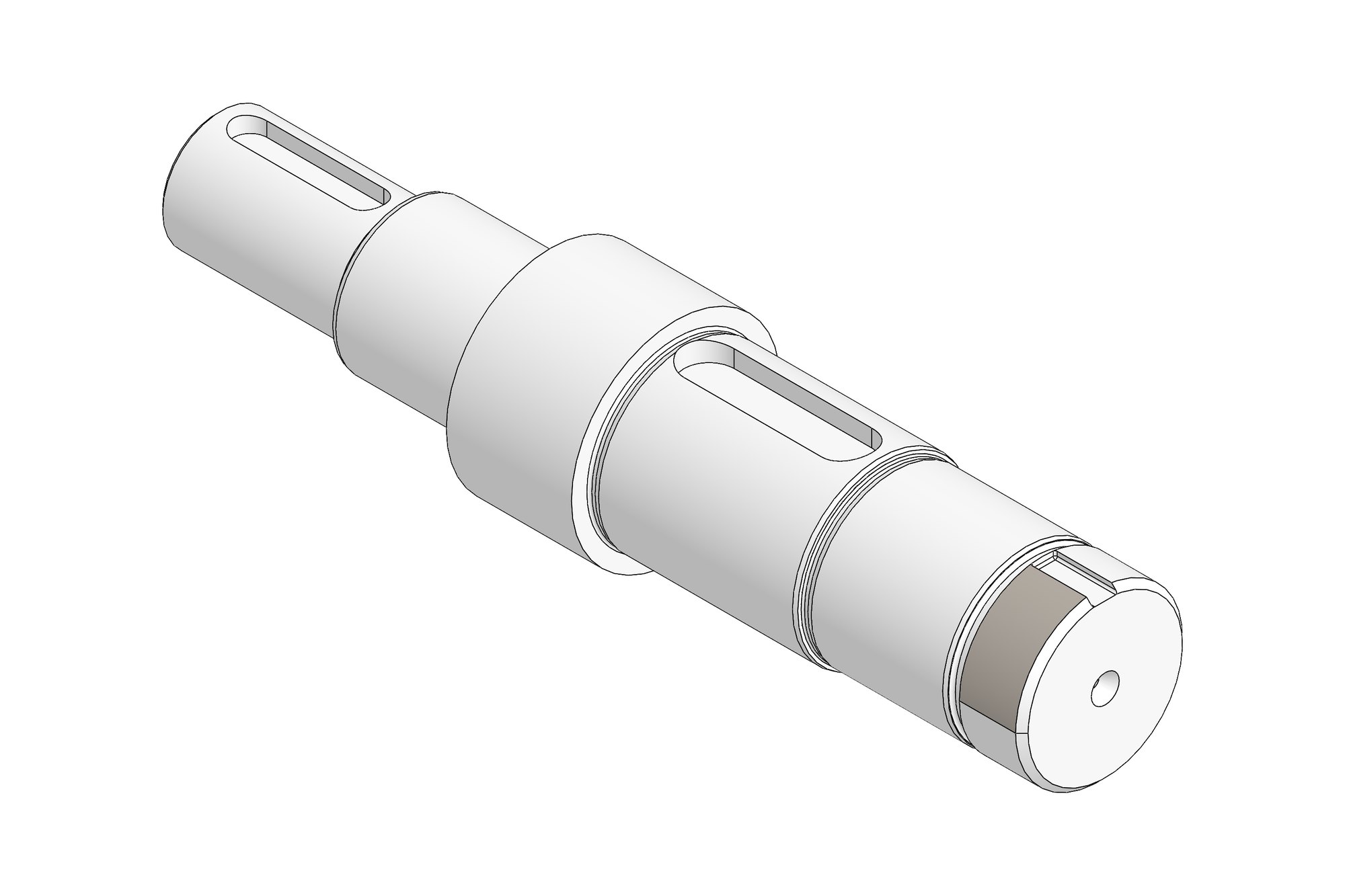
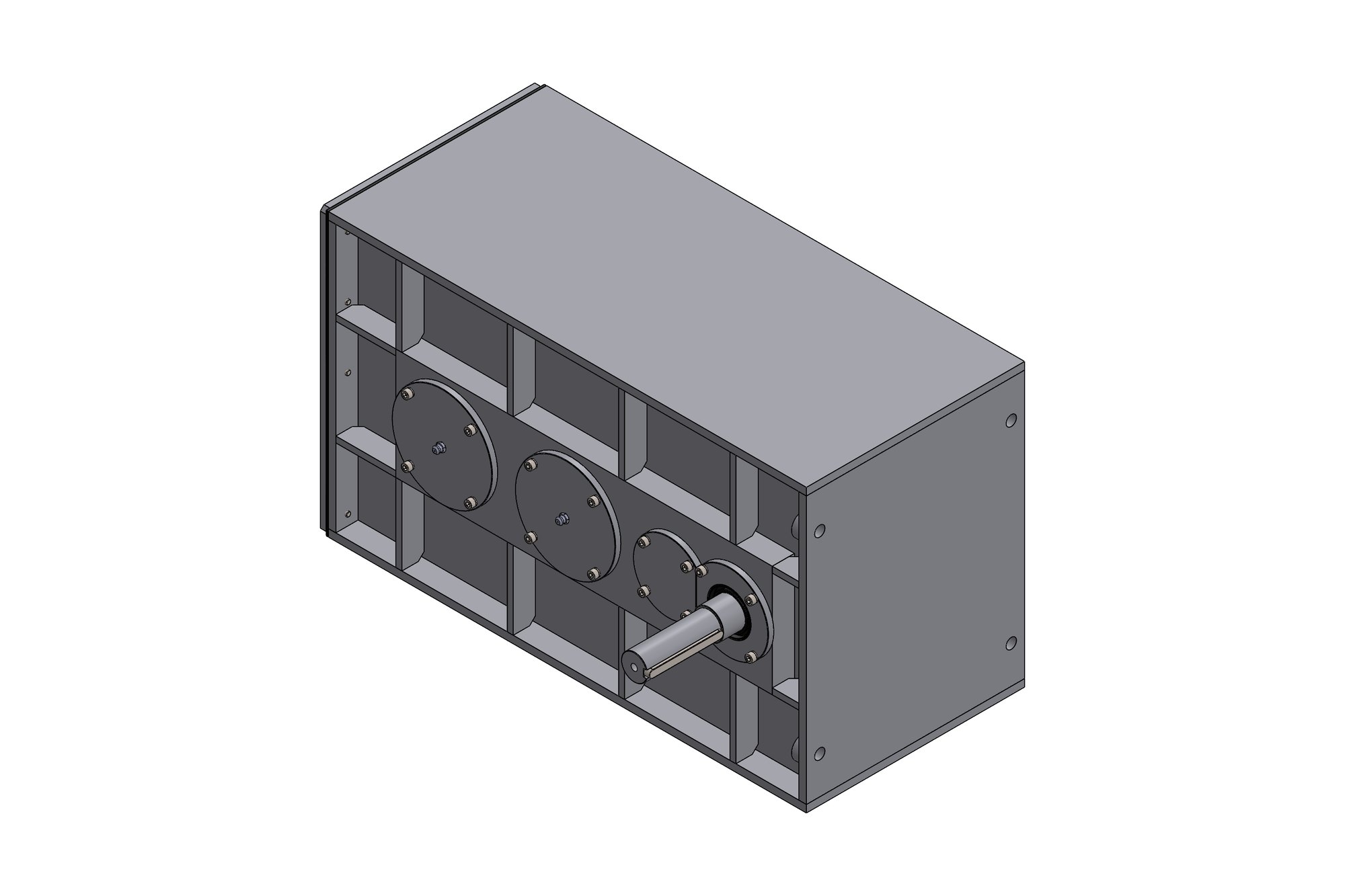
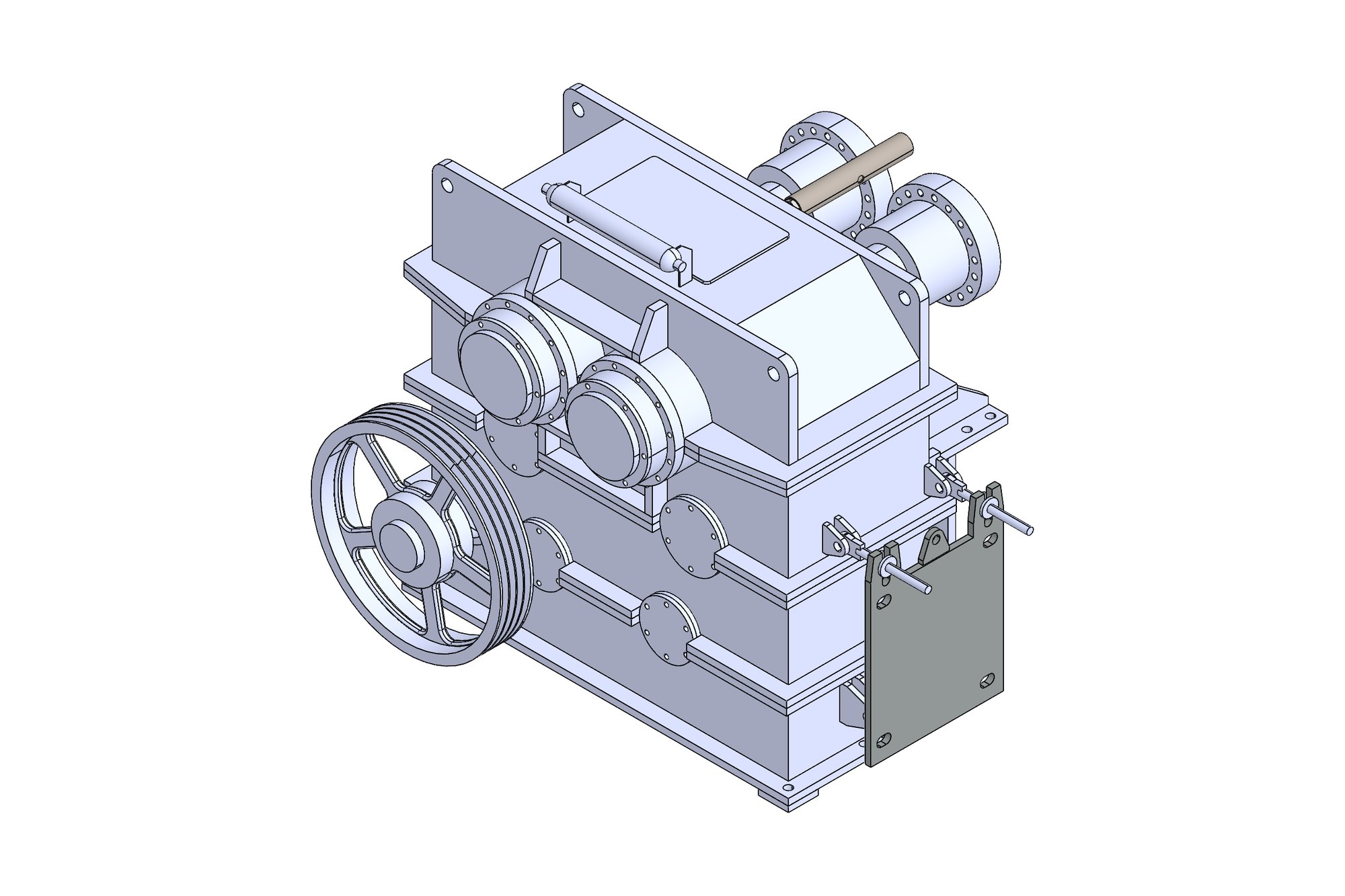
We modelled every part in Solid Edge from the 2D sheet: the cast housing with its bearing bores and inspection cover, the input shaft with the flywheel seat, the gear shafts and wheels, taper-roller bearings, bearing covers, oil seals and the spoked flywheel. Where the old drawing was silent — a fillet radius, a seal diameter — we applied the manufacturer's own standard practice from their other units and flagged the value on the drawing.
The assembly was checked for interference and for the timing of the two output shafts through the gear train, and sections were cut at each bearing position to confirm the stack-up of spacers, bearings and covers that the parts list implied.
From the model we produced a new GA with a numbered BOM, a part drawing for every machined component with ISO fits on bores and shafts, and a flywheel drawing with keyway and balance note, all on the manufacturer's AutoCAD title block.
What was delivered
The gearbox now exists as a maintained 3D assembly and a complete drawing set. New orders are issued from the model, spares are quoted from the BOM, and the one old 2D sheet has been retired.
- Solid Edge assembly and part models
- GA drawing with numbered BOM
- Part drawings for housing, shafts, gears, covers and flywheel
- DWG set on the manufacturer's title block
- STEP export for pattern and machining suppliers
Standards and conventions applied
- ISO 286 fits on shafts and bores
- ISO 2768 general tolerances
- Manufacturer drawing standard and numbering
Have a similar requirement? Send the drawings, a sketch or a description — an engineer will scope it and reply with an itemised quote within one business day. Request an engineering quote.