- Client
- Shree Geeta Gear — Gear manufacturer, Ahmedabad
- Industry
- Gearboxes & Power Transmission
- Service
- Reverse Engineering
- Platform
- SolidWorks
- Client region
- India
- Inputs
- Customer 3D scan data, brass sample parts, feed box manual
- Output
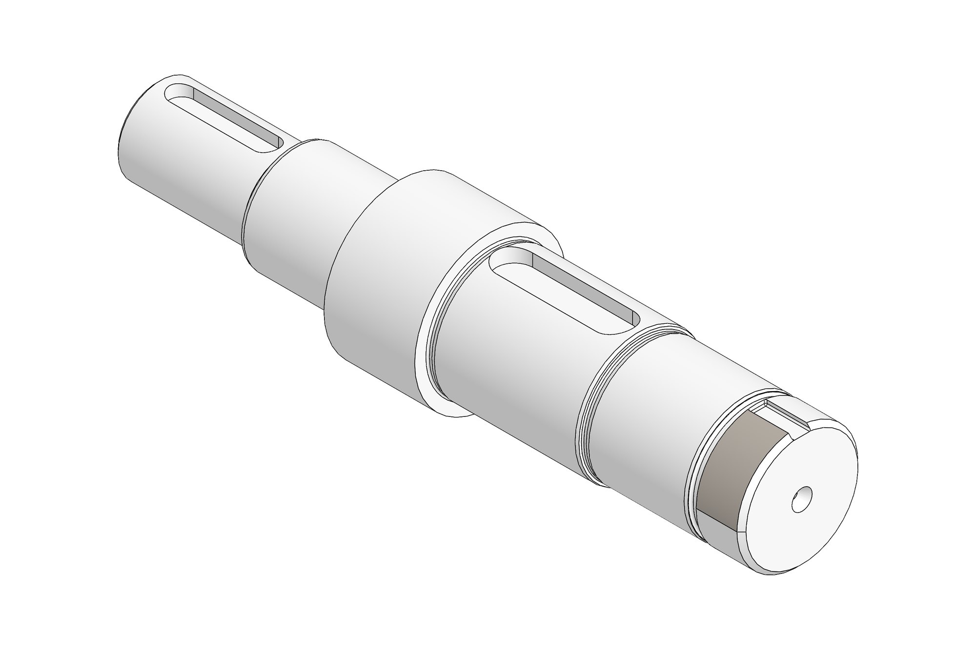
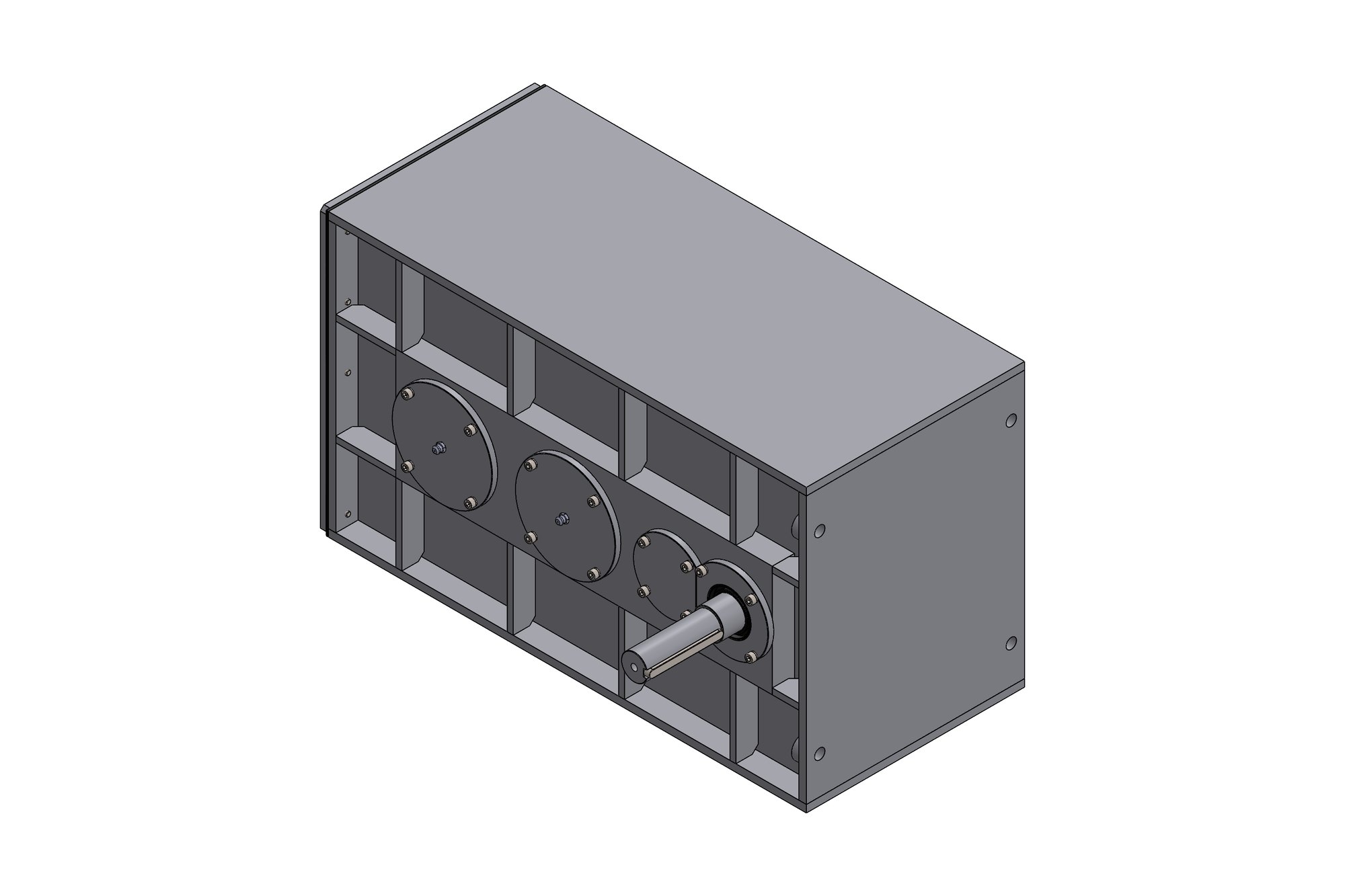
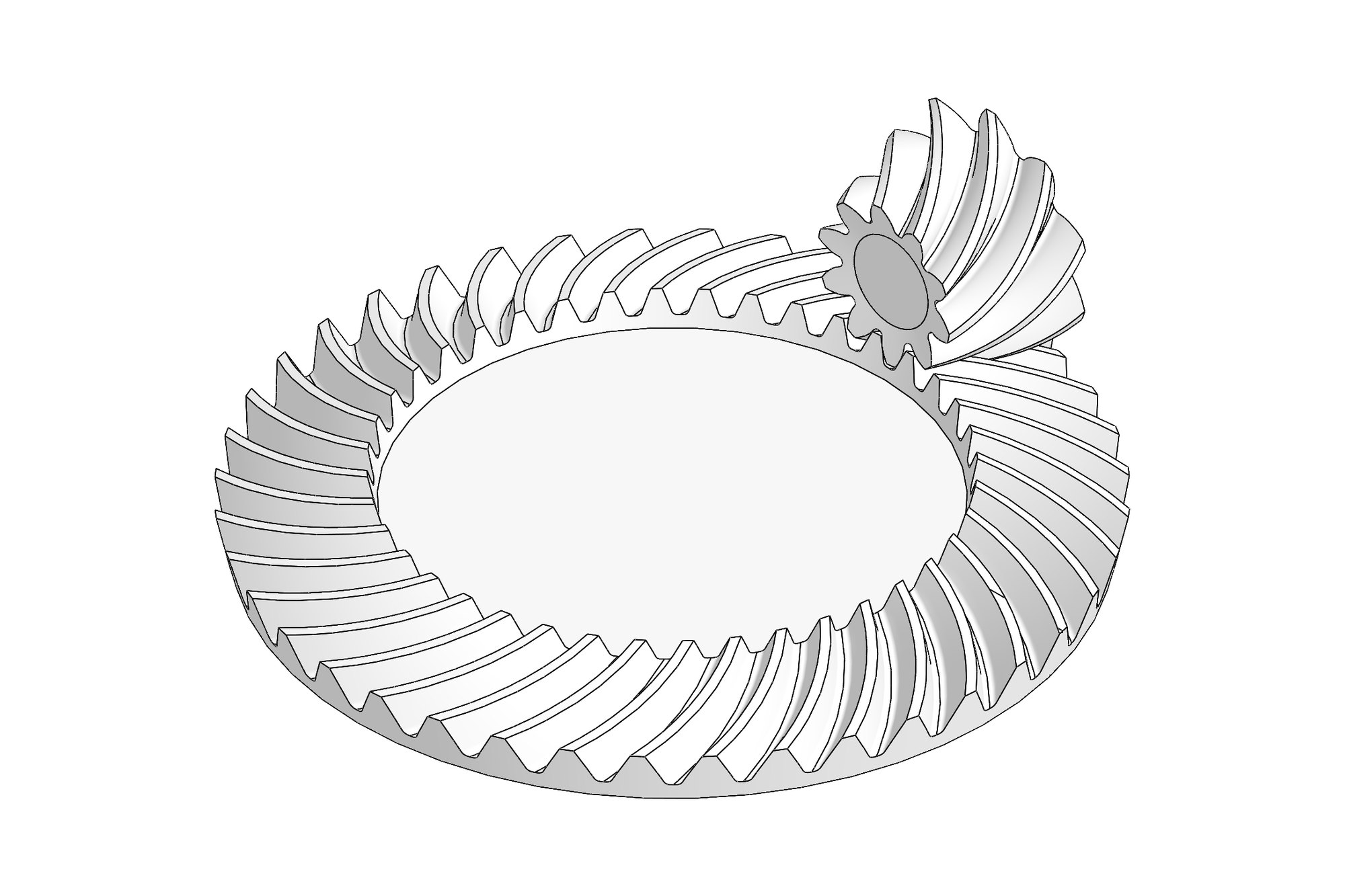
- Parametric parts, assembly, STEP per revision
- Revisions
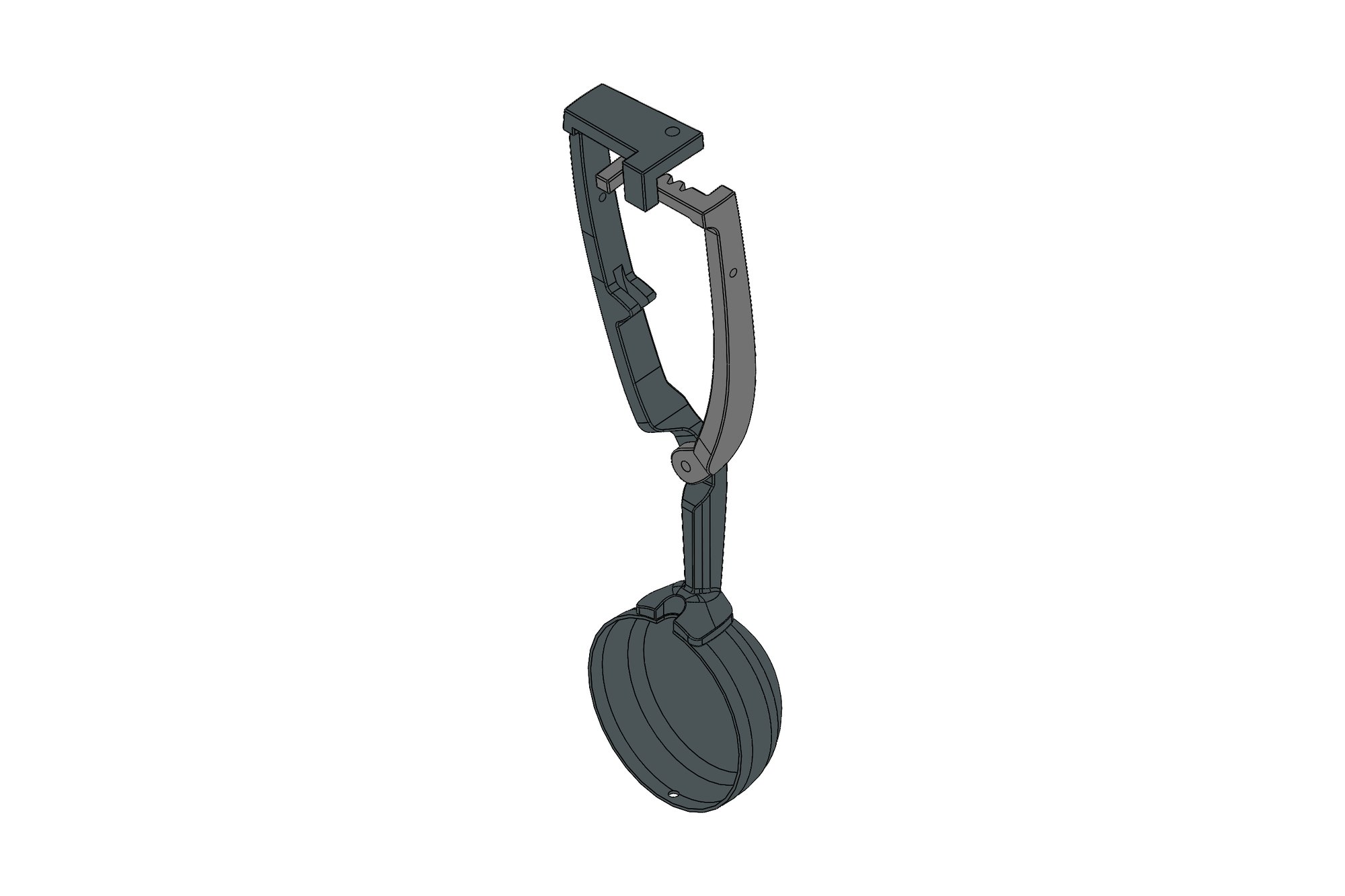
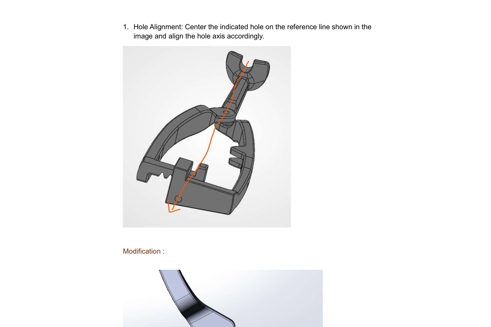
- Scoop revision 3 and 4; hole alignment modification sheet
The challenge
Scan data shows the worn as-built part, not the design intent: a bore that has worn oval, a hole drilled slightly off on the original casting. The rebuilt parts had to be made to the intended geometry — true cylinders, holes on their design axes — while still fitting the mating parts that were not being replaced.
Our approach
We worked from the client's scan meshes in SolidWorks, establishing reference planes and axes from the best-preserved surfaces, then modelling each part parametrically with nominal dimensions rounded to design values rather than scan readings. Where a hole axis did not sit on the reference line, the modification sheet recorded the previous position and the shifted position so the client could agree the correction before it was made.
Scoop and brass part revisions were issued as numbered STEP files with a modifications PDF per round, and the client fitted each revision to their mating parts and returned measurements until the assembly checked.
What was delivered
The client manufactured the feed box parts from the final STEP data and drawings, with the modification sheets serving as the record of every departure from the scan.
- Parametric SolidWorks parts and assembly
- STEP files per revision
- Modification sheets documenting corrected positions
- Manufacturing drawings
Standards and conventions applied
- Design-intent modelling from scan data
- ISO 2768 general tolerances
- Datum-based hole position control
Have a similar requirement? Send the drawings, a sketch or a description — an engineer will scope it and reply with an itemised quote within one business day. Request an engineering quote.