- Client
- Industrial gearbox builder, Gujarat (name withheld under NDA)
- Industry
- Gearboxes & Power Transmission
- Service
- Machine & Equipment Design
- Platform
- SolidWorks, KISSsoft
- Client region
- India
- Duty
- 25 kW · 1750 rpm · ratio 6.33 (actual 6.3529)
- Gear train
- 17/36T × 3 M · 17/51T × 4 M · 40/40T × 4 M LH/RH
- Package
- 70 parts · 36-item BOM · 24 drawings
The challenge
The brief was a short text file: ratio 6.33, 25 kW motor, 1750 rpm input. Everything else — centre distances, tooth counts, helix angles, bearing sizes, the housing construction and how the unit would be assembled and inspected — had to be decided by us and justified in the drawing set.
Two output gears were required, one left-hand and one right-hand, so that two driven shafts rotate in opposite directions from a single input. Both have to sit on exactly the same centre distance from the second-stage pinion, which fixes the housing bore pattern to a tight positional tolerance before anything is machined.
Our approach
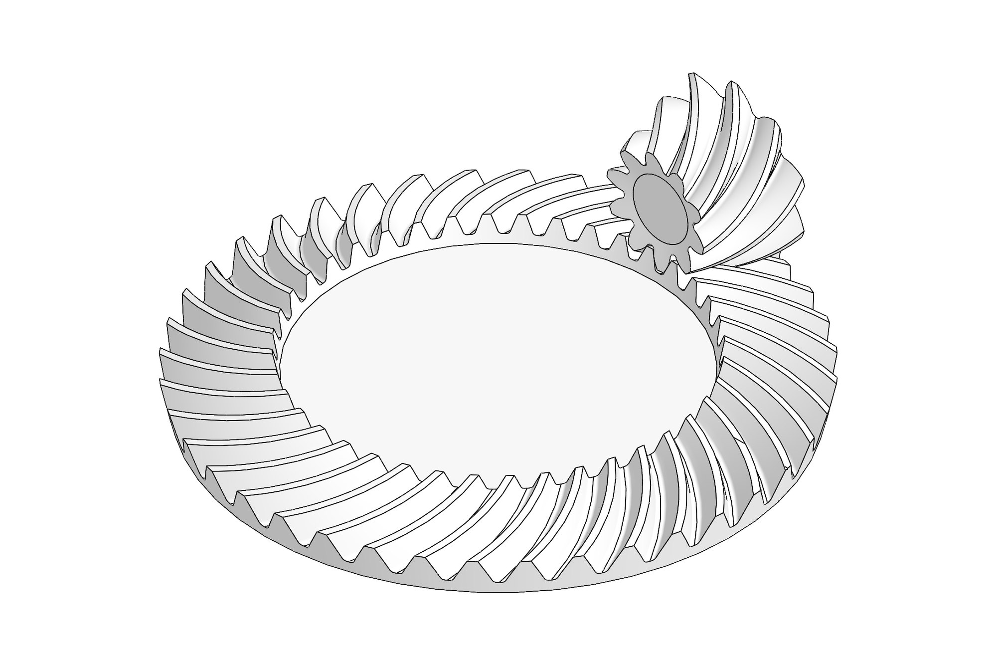
The train was laid out as a 17T/36T × 3 module input stage followed by a 17T/51T × 4 module second stage, which together give 6.3529 — within one percent of the requested 6.33 — with both stages on standard cutter modules. The second-stage wheel is a 51T × 4 M helical with a 10° left-hand helix, carburised to 58–62 HRC with 0.8 mm case depth, cut to DIN 8 accuracy with a base tangent length of 67.795/67.842 mm over 6 teeth so the gear cutter can inspect it on the bench.
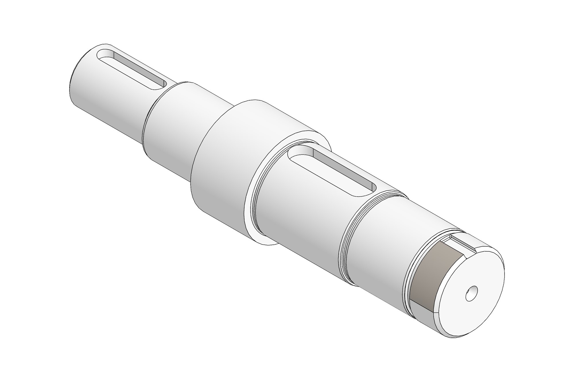
Each pair was rated in KISSsoft for the 25 kW duty and the face widths, helix angles and materials were fixed from those reports rather than estimated. Taper-roller bearings carry the axial component of the helical meshes, with closed and open input covers and two drive shafts detailed with keyways and seal diameters.
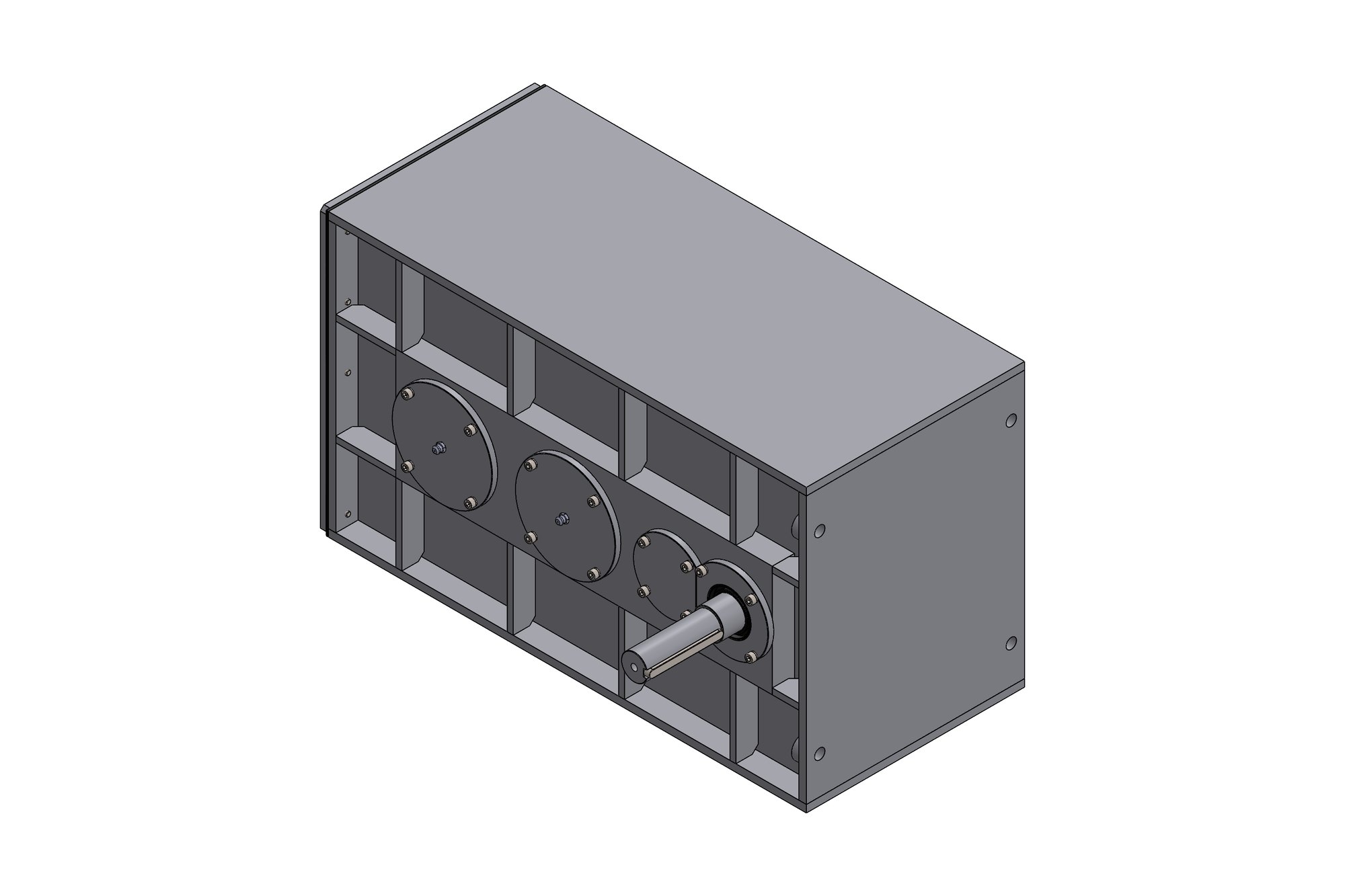
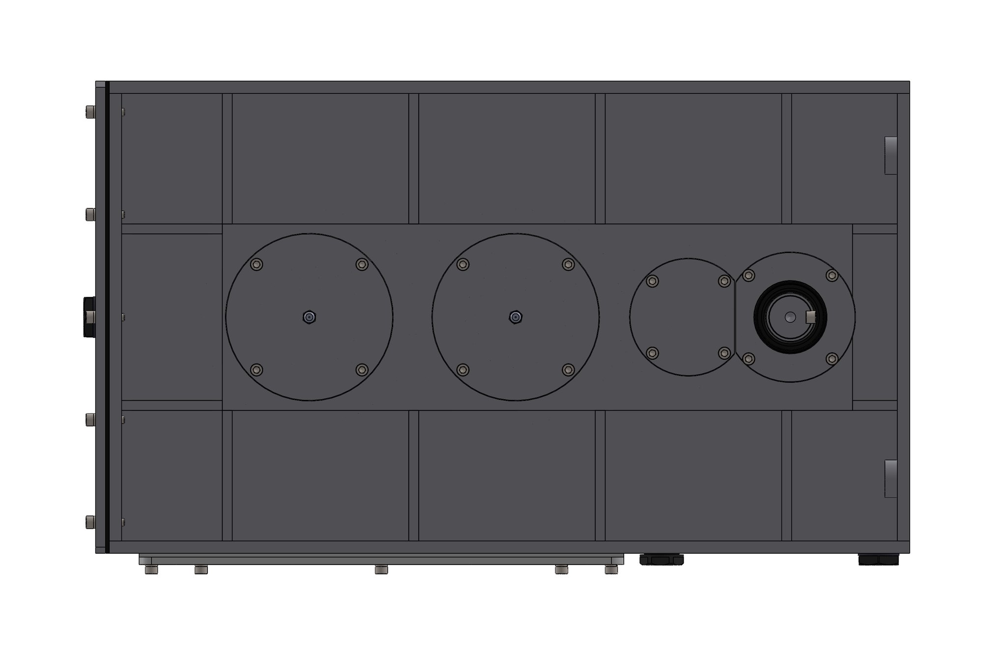
The housing is a fabricated box with a bolted top cover, 3 mm gaskets for both covers and an acrylic inspection cover so the mesh can be checked at commissioning. The general-arrangement drawing carries a 36-item BOM with a drawing number for every part (000-01 to 000-36), plus sectional views through both stages with the running fits on every bearing seat and shaft (k6, m6 shafts; H7 bores).
What was delivered
The customer received the SolidWorks assembly, a GA with sectional views and the full BOM, 24 part drawings with gear data tables and heat-treatment notes, KISSsoft rating reports, DXF profiles for the gaskets and STEP files for the housing fabrication. The gearbox was built from the first issue of the drawings.
- SolidWorks assembly (70 parts) with configurations
- GA drawing with 36-item BOM and sections A-A / B-B
- 24 part drawings with gear data and heat-treatment notes
- KISSsoft rating reports for both helical stages
- STEP and DXF files for fabrication
Standards and conventions applied
- ISO 6336 helical gear rating (KISSsoft)
- DIN 3962 gear accuracy grade on gear drawings
- ISO 286 fits (k6 / m6 / H7) on shafts and bores
- Customer title block, tolerance table and numbering
Have a similar requirement? Send the drawings, a sketch or a description — an engineer will scope it and reply with an itemised quote within one business day. Request an engineering quote.