- Client
- Industrial gearbox builder, Gujarat (name withheld under NDA)
- Industry
- Gearboxes & Power Transmission
- Service
- Machine & Equipment Design
- Platform
- SolidWorks, KISSsoft
- Client region
- India
- Gear pair
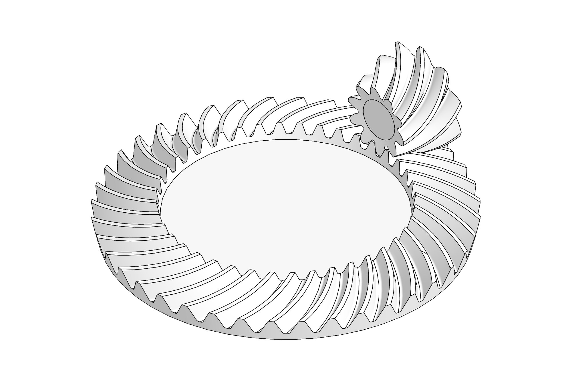
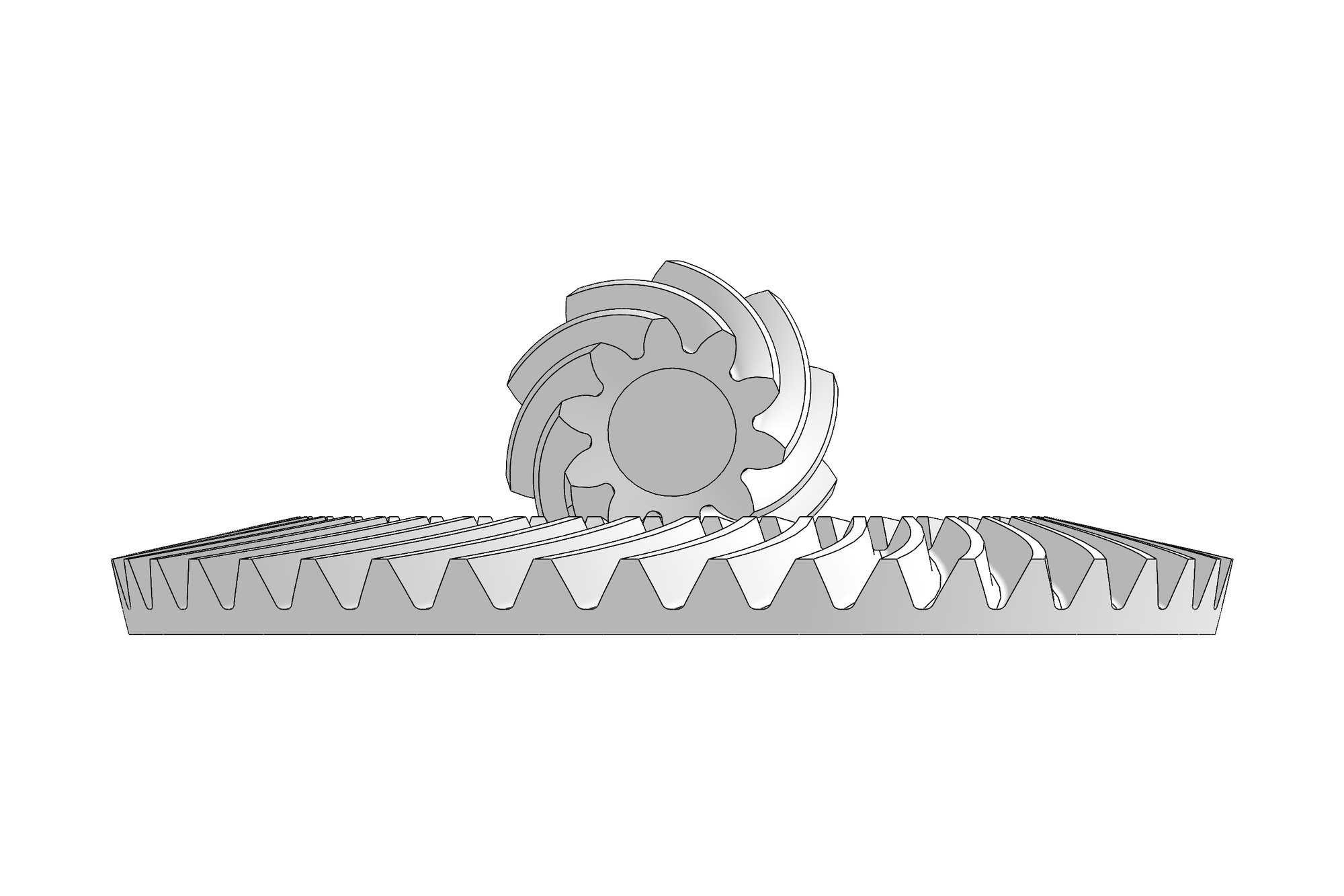
- 40T crown · 10T pinion · module 3.11 · 90° shaft angle
- Geometry
- Spiral angle 34.495° · pitch angle 75.96° · backlash 0.13–0.18
- Rating
- KISSsoft 2022 SP5 · ISO 10300 incl. scuffing (ISO/TS 10300-20)
The challenge
The existing unit was a catalogue right-angle gear unit with a hollow input shaft, bevel pinion, output bevel wheel, two bearing housings, a motor plate and side covers. The customer had its drawings but not the gear design behind it, and a 10-tooth pinion against a 40-tooth crown gear is an aggressive pair that cannot simply be copied — the tooth profile, spiral angle and strength all have to be checked.
The new pair also had to carry 15 kW continuously and fit inside the same housing envelope with the same bearing positions, so the mounting distances and the crown gear back-cone geometry were fixed before the tooth design started.
Our approach
We built the bevel pair in KISSsoft from the required ratio and the available cone distance: module 3.11 at the outer end, a 34.495° spiral angle, 20° pressure angle and a 90° shaft angle. The 13-page report covers tooth geometry, the equivalent spur gear, contact lines, K-factors, root bending and flank pitting safeties and scuffing capacity to ISO/TS 10300-20 with flash temperature, so the customer has a complete rating file for the pair, not just a drawing.
The crown gear drawing carries the full gear data block — 40 teeth, pitch diameter, pitch angle 75.96°, face angle 77.26°, root angle 72.12°, addendum 2.131, dedendum 6.208, backlash 0.13–0.18 mm and mating gear 10T — together with the bore, mounting-distance and runout tolerances the gear cutter and the assembler both need.
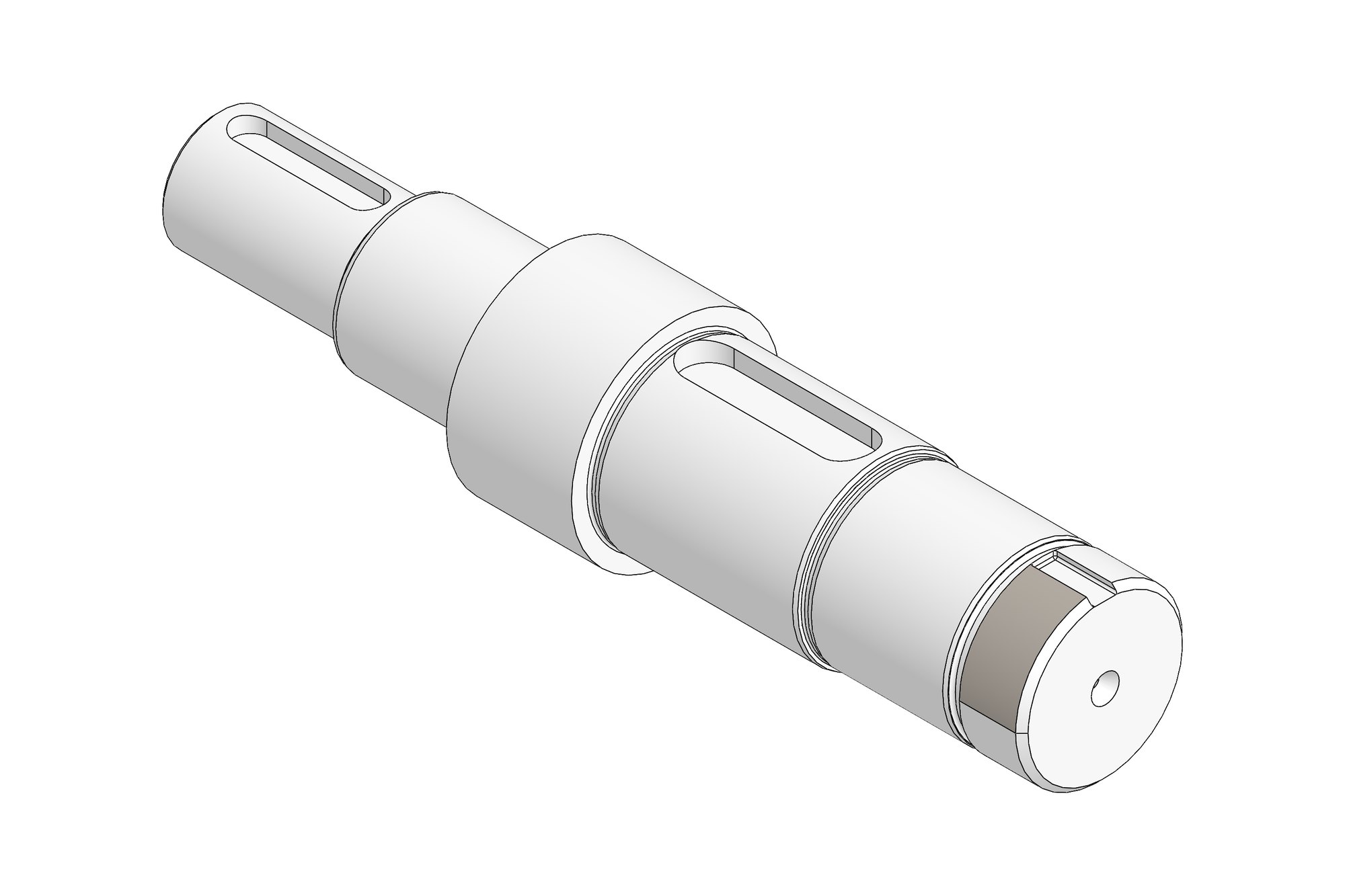
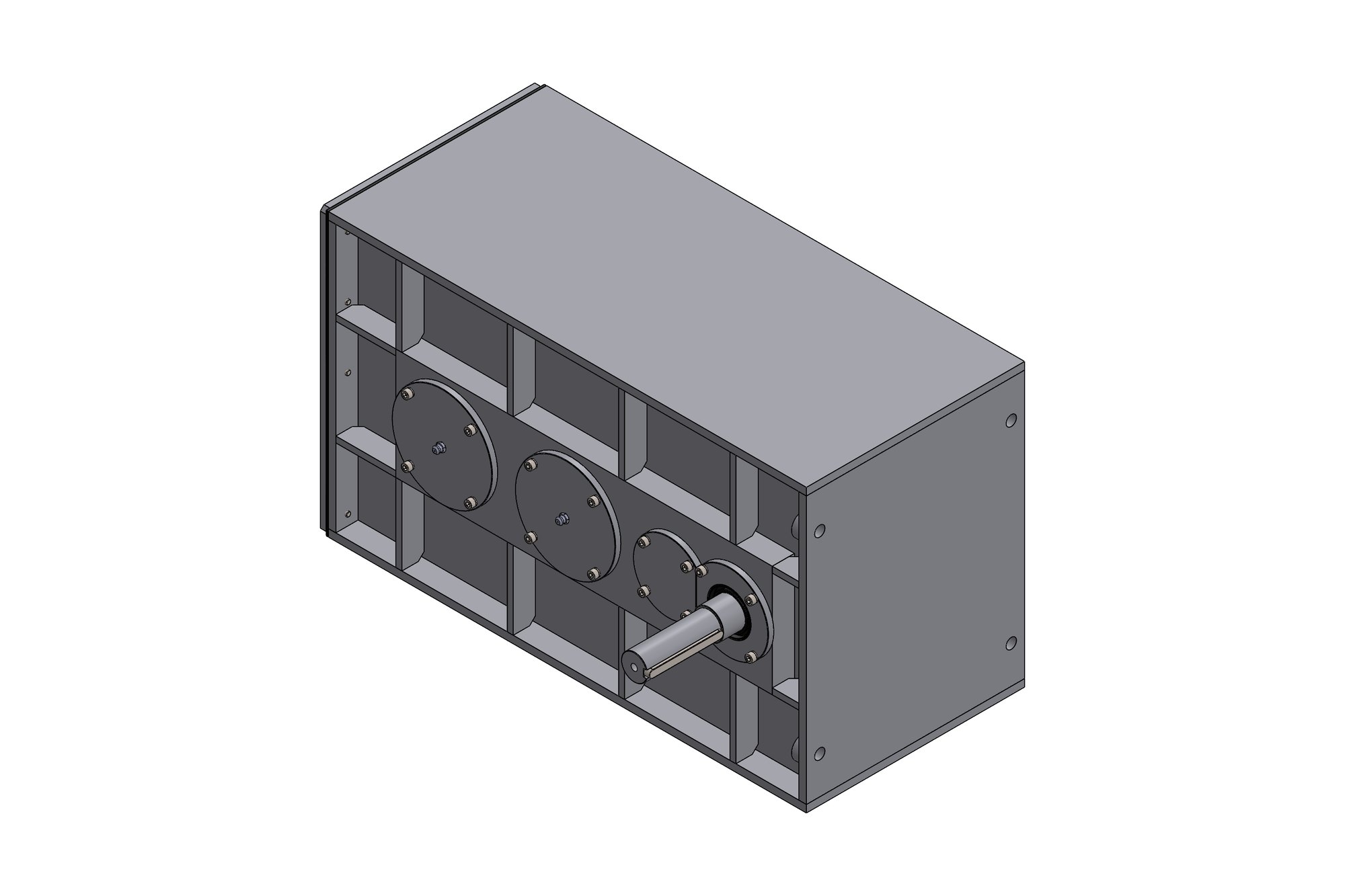
Around the pair we modelled and detailed the hollow output shaft, the gearbox housing and the input housing in SolidWorks, reusing the customer's bearing sizes (30309, 30312 and 31313 taper rollers). Each machined part was issued as a drawing, a DXF for profile cutting where relevant, and a STEP file.
What was delivered
The customer received the KISSsoft rating report, the crown gear and pinion drawings with complete gear data, hollow output shaft and housing drawings, the SolidWorks assembly and STEP/DXF exports. The pair was cut on their own spiral bevel generator from this data.
- KISSsoft bevel gear report (13 pages) with ISO 10300 rating
- Crown gear and pinion drawings with gear data block
- Hollow output shaft, housing and input housing drawings
- SolidWorks assembly with bearings and covers
- STEP and DXF exports for every machined part
Standards and conventions applied
- ISO 10300 bevel gear rating including ISO/TS 10300-20 scuffing
- ISO 23509 bevel gear geometry
- ISO 286 fits on bores and shafts
- Customer title block and tolerance table
Have a similar requirement? Send the drawings, a sketch or a description — an engineer will scope it and reply with an itemised quote within one business day. Request an engineering quote.