- Client
- Industrial valve manufacturer, Gujarat (name withheld under NDA)
- Industry
- Pumps, Valves & Fluid Handling
- Service
- CAD Conversion & Migration
- Platform
- SolidWorks
- Client region
- India
- Valve
- 250 NB, Class 150, Y-type bellow-seal globe, flanged
- Parts modelled
- Body, bonnet, plug, stem
- Flanges
- 16 × Ø17.5 on Ø415 PCD / 12 × Ø25.4 on Ø361.9 PCD per drawing
The challenge
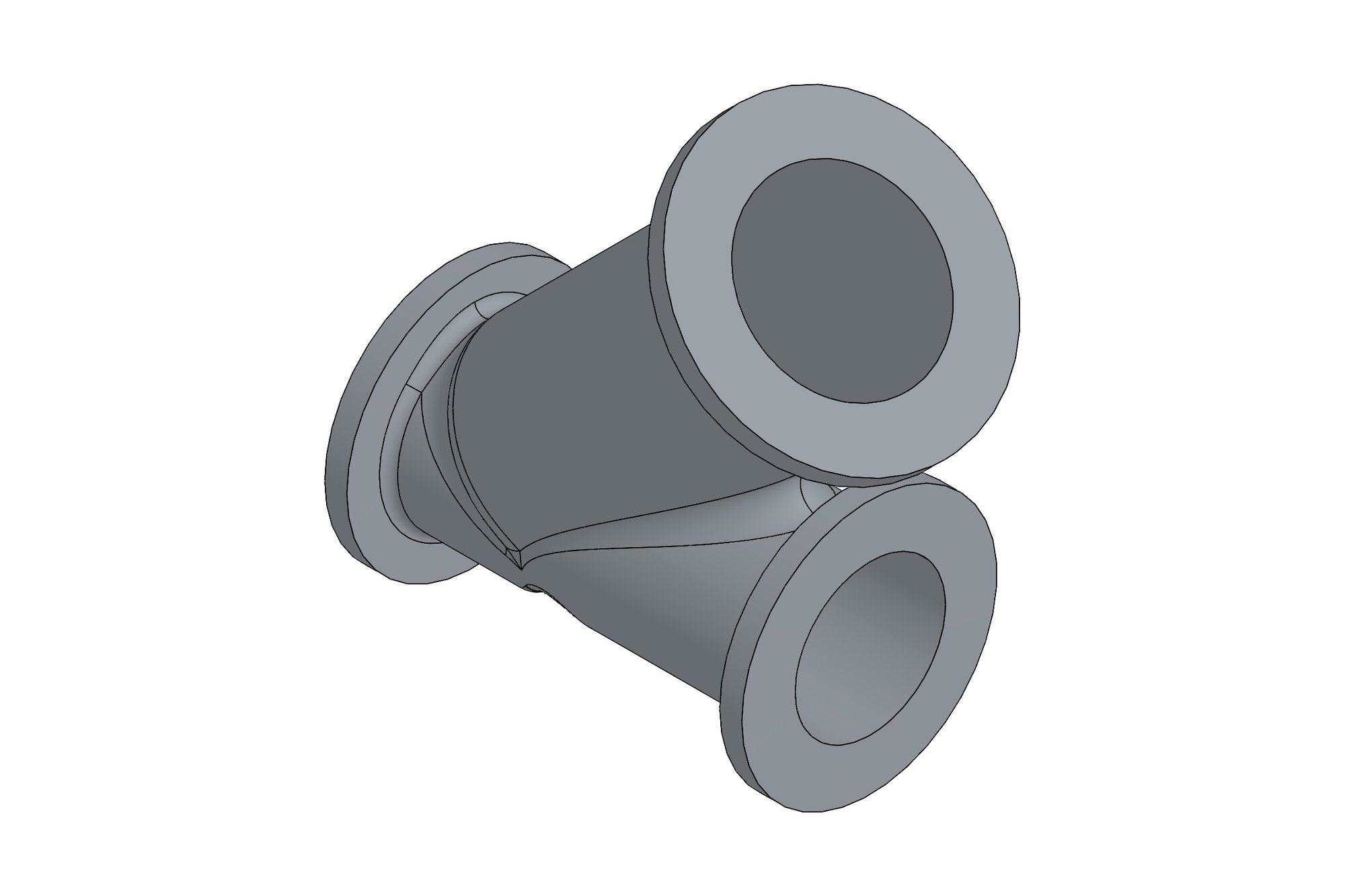
Valve bodies are castings with a machined flow path, and the 2D drawings describe both the casting and the machining on one sheet. The model had to separate the two cleanly — as-cast geometry with allowances and the finished machined faces, flange drilling and seat — so that the maker could use it for pattern work, machining and catalogue illustrations.
Our approach
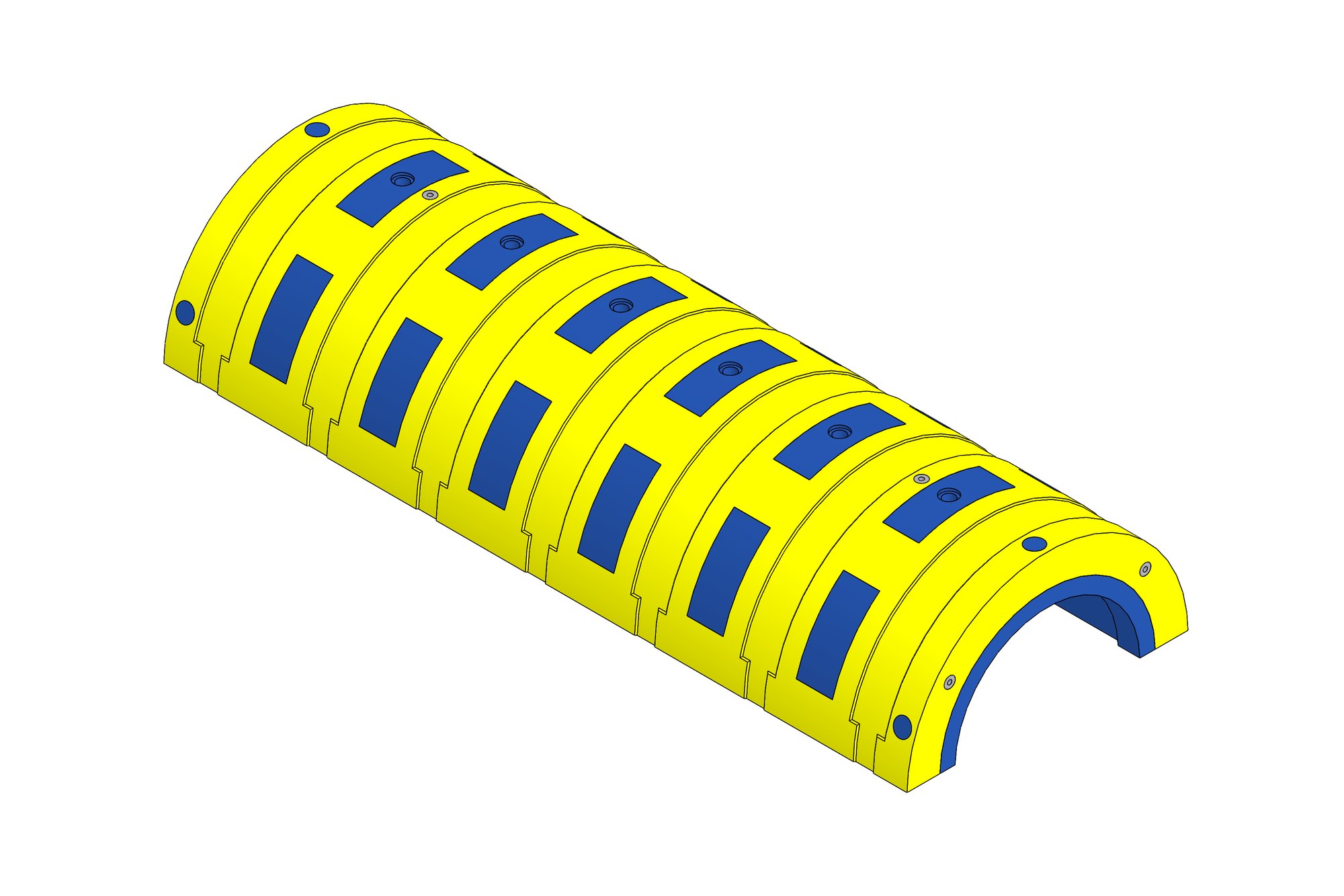
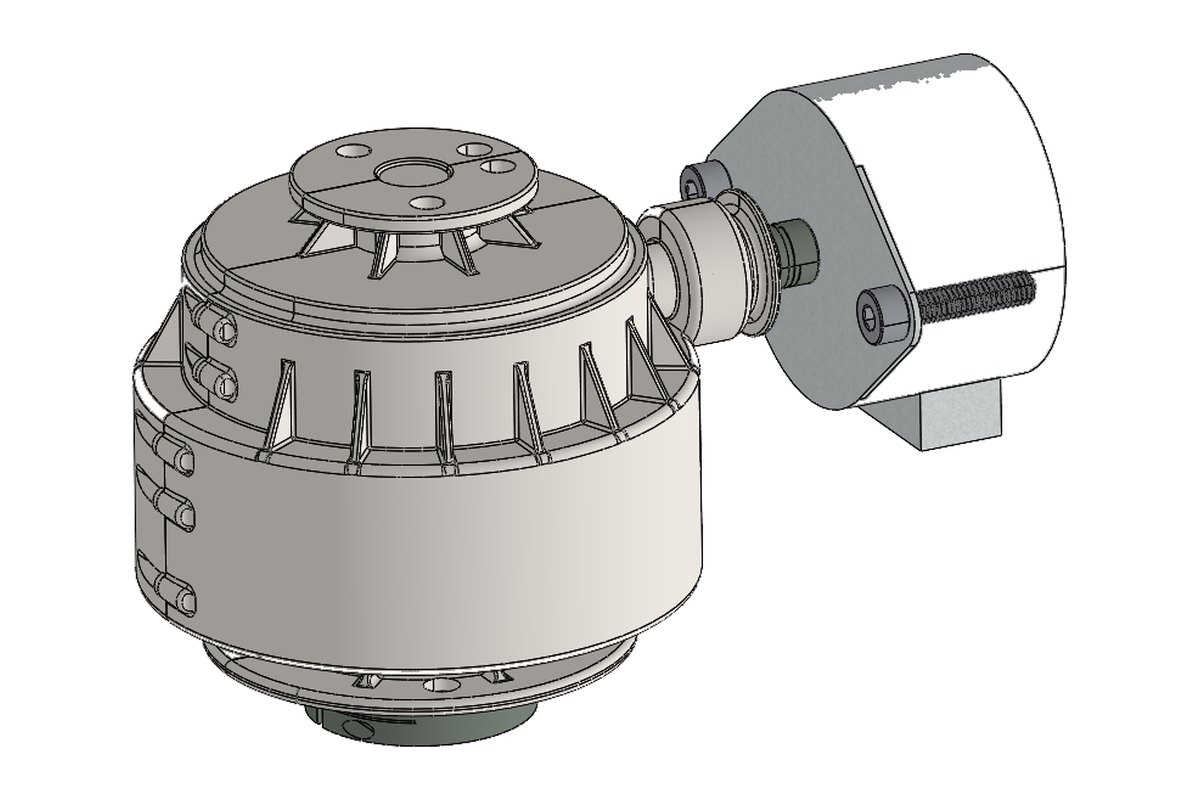
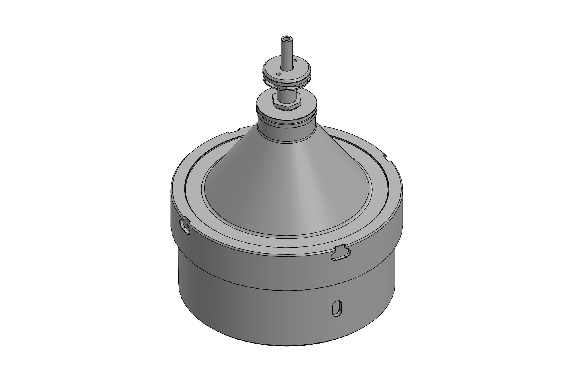
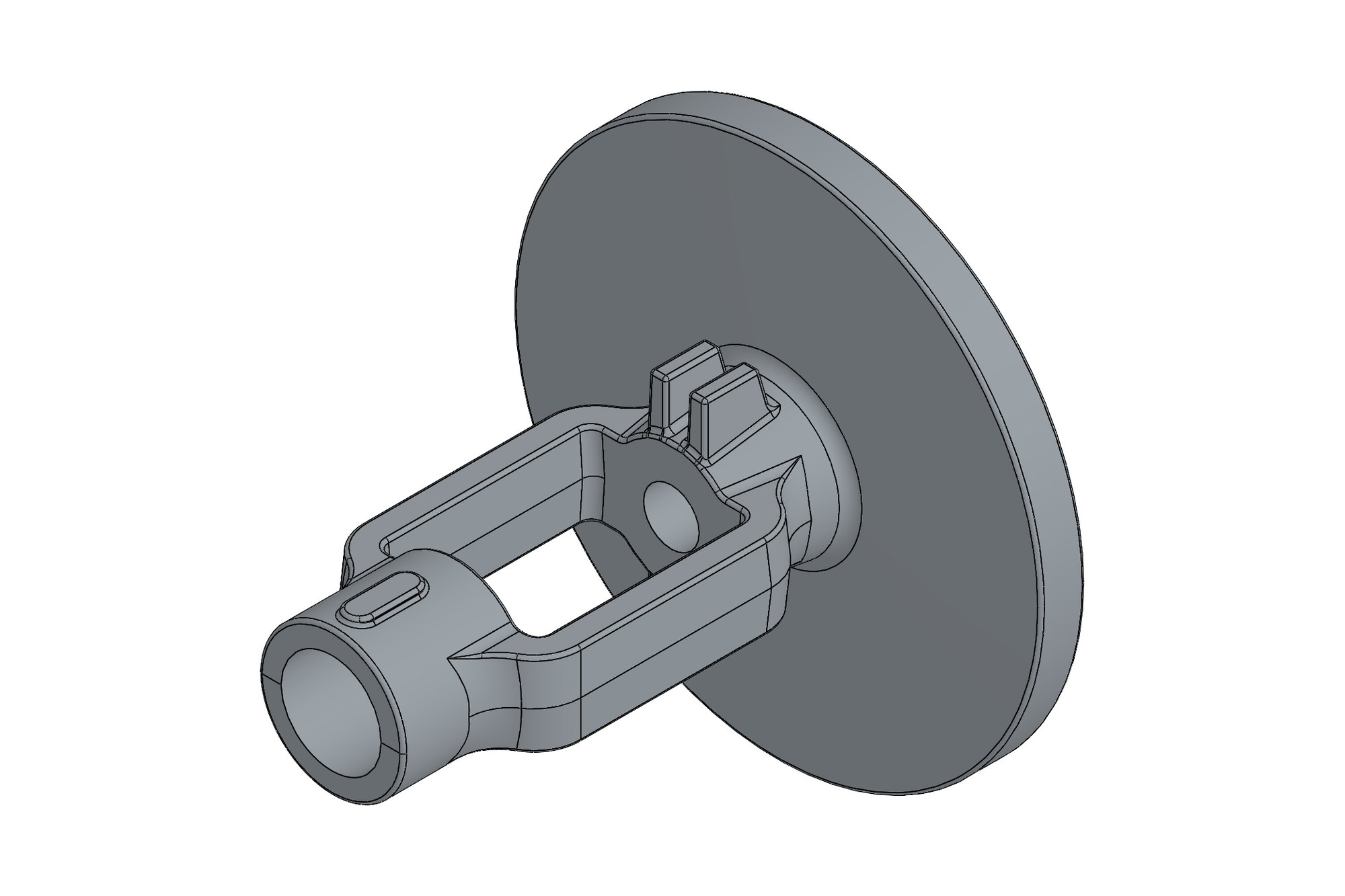
The body was modelled as a cast part with the Y-type flow path, then machined features added as separate features: the end flanges with their drilling patterns, the seat bore and the bonnet joint. Bonnet, plug and stem were modelled to their drawings with the bellow and packing areas as the drawing defined them, and the four parts mated into a valve assembly in the closed position.
Every dimension on the source drawings was ticked off against the model, and the few ambiguities — a wall thickness implied rather than dimensioned — were listed on a query sheet and confirmed with the maker before release.
What was delivered
The maker received native SolidWorks parts and assembly, STEP files and a query sheet closed with their answers, and now produces catalogue sections and machining programmes from the model.
- SolidWorks parts for body, bonnet, plug and stem
- Mated valve assembly
- STEP exports
- Query sheet with resolved items
Standards and conventions applied
- Flange dimensions as defined on the maker's drawings
- ISO 2768 general tolerances
- Casting and machining features separated in the model
Have a similar requirement? Send the drawings, a sketch or a description — an engineer will scope it and reply with an itemised quote within one business day. Request an engineering quote.