- Client
- Offshore and marine systems manufacturer, Ahmedabad (name withheld under NDA)
- Industry
- Pumps, Valves & Fluid Handling
- Service
- 3D Modelling & 2D Drafting
- Platform
- Autodesk Inventor
- Client region
- India
- Scope
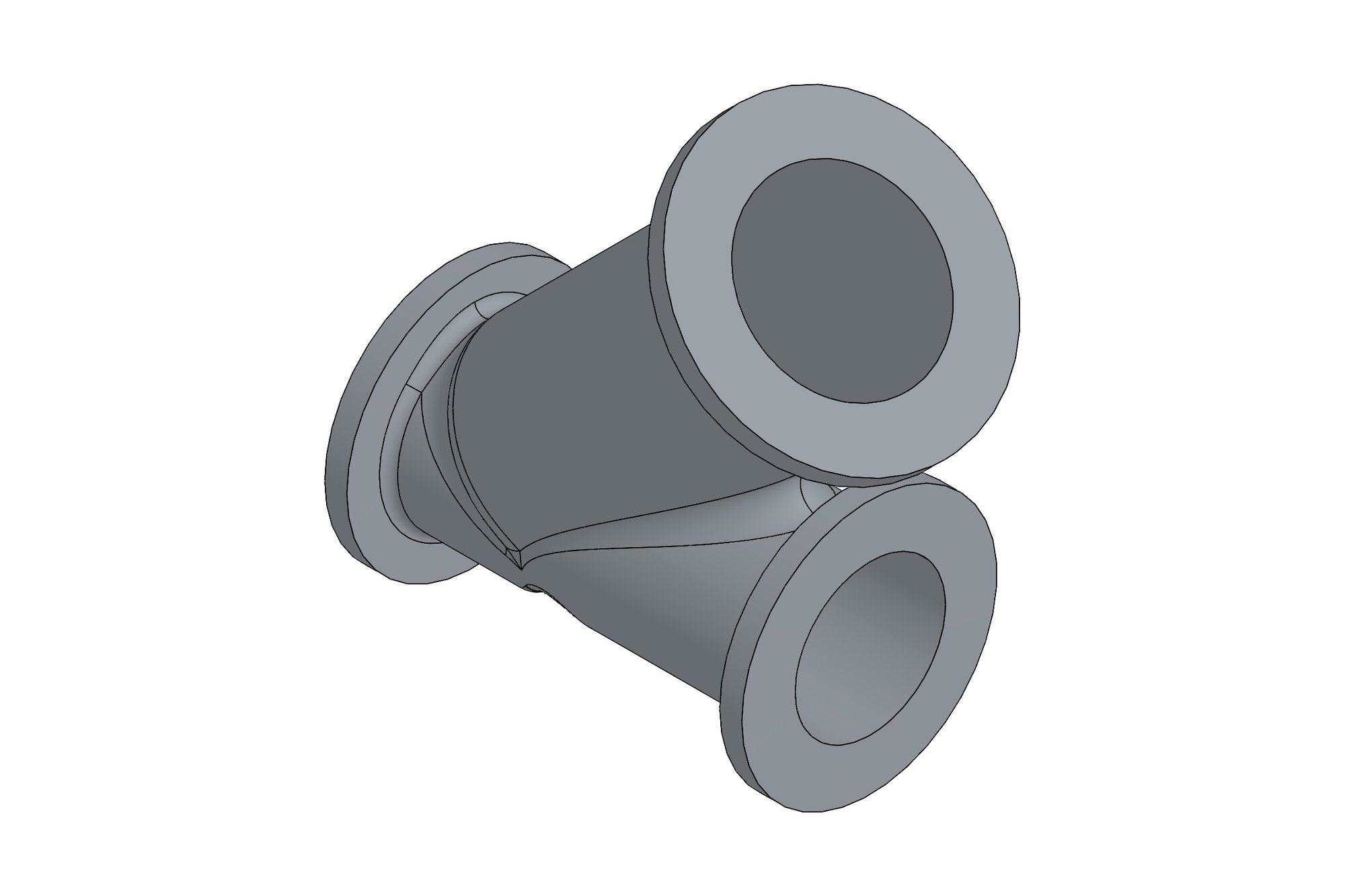
- 6 shroud assemblies · insulation cover · 2 moulding tools
- Model
- 38 Inventor assemblies · 277 parts · inner/outer pipe pups, welds, 3LPP and HSS coating layers
- Tooling
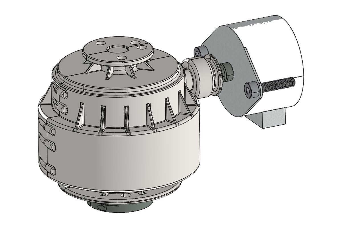
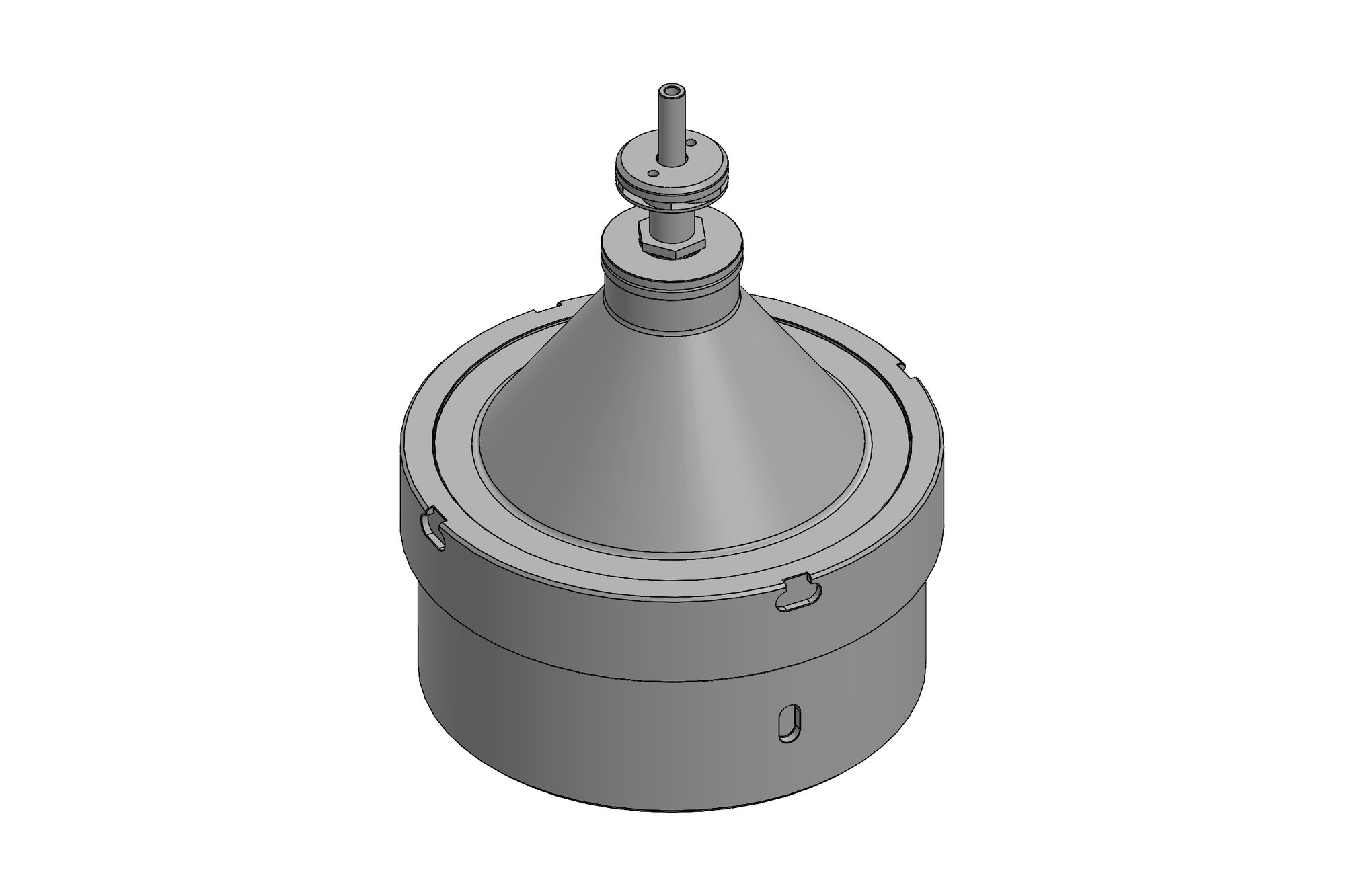
- Base plate and core · cavity · fill plate · inserts · vent plate · A1 drawings
The challenge
The client runs Inventor with a project workspace, templates and a part-numbering system that every file must respect, because the models feed their own drawing office and their manufacturing. Work had to be done inside that workspace, not converted in and out of another CAD system.
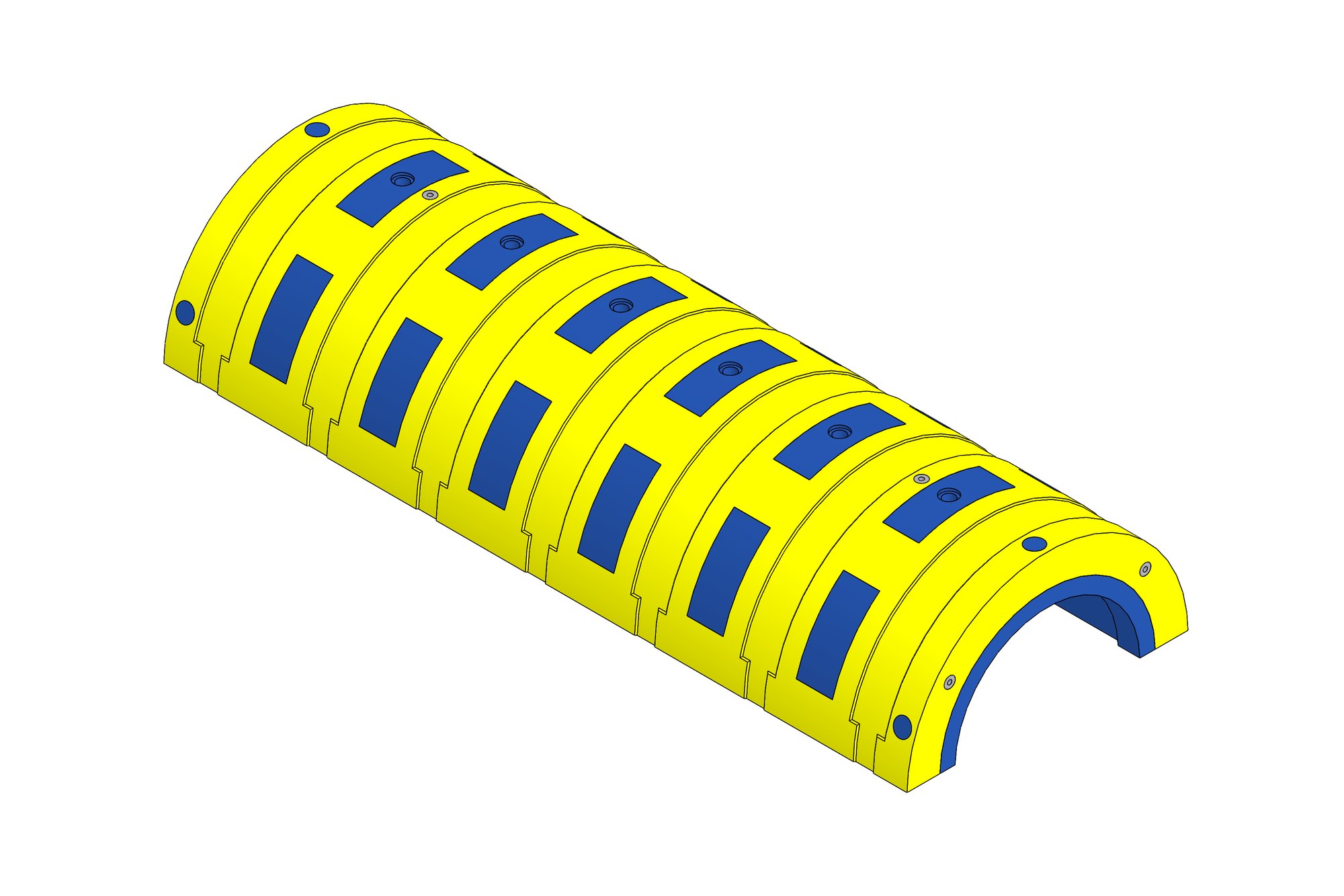
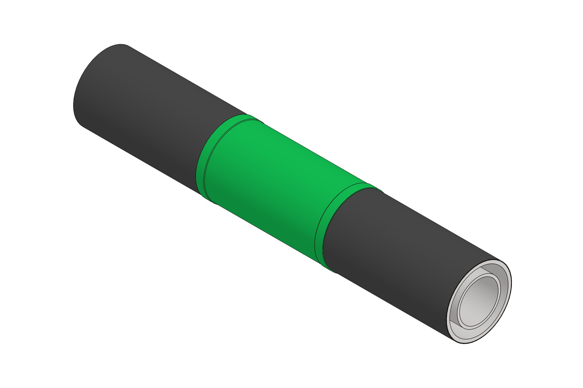
A shroud is not one part: it is inner and outer pipe pups and weld sections, the external coating layers modelled as their own bodies, the polymer insulation, the marking and the steel work that holds it together. Each layer has its own drawing and its own supplier. The moulding tools then have to be derived from the cover geometry with shrinkage and draft, and split into base, cavity and inserts that can be machined and assembled.
Our approach
Six shroud assemblies were built in Inventor from the client's pipe data: inner pipe pups and welds, outer pipe pups and welds, the three-layer polypropylene external coating and the high-shear coating as separate parts, the marking and the steel-work sub-assembly. Each assembly carries its own A1 drawing on the client's template with the parts list driven from the model.
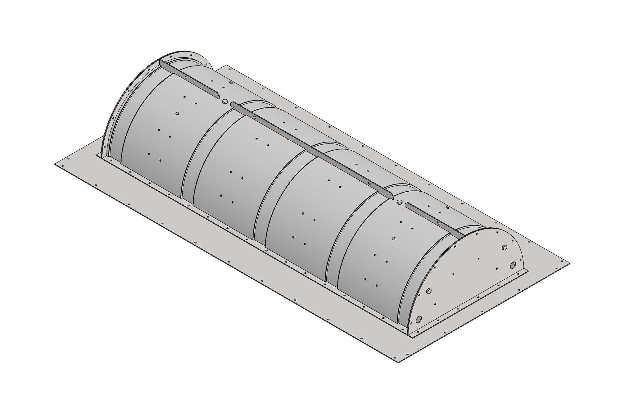
For the insulation cover we derived the two moulding tools from the cover geometry: a base plate and core, a cavity, a fill plate, two inserts and a vent plate for each tool, with the split lines, draft and vent positions set so the polymer fills and releases. The tools were issued as their own assemblies and drawings in the same numbering series.
All files were delivered back into the client's workspace structure — designs, projects, resources and templates — so their drawing office opened them without relinking.
What was delivered
The client received 38 Inventor assemblies and 277 parts across six shrouds, one insulation cover and two moulding tools, with A1 drawings on their template and the files placed in their own project structure.
- Inventor assemblies for 6 shrouds (38 assemblies, 277 parts)
- Insulation cover model with coating layers
- Two moulding tool assemblies (base/core, cavity, fill plate, inserts, vent plate)
- A1 drawings on the client's Inventor template
- Files delivered inside the client's workspace
Standards and conventions applied
- Client Inventor template, numbering and workspace structure
- ISO GPS tolerancing on tooling drawings
- DNV-RP-F106 / ISO 21809 coating references on shroud sheets
Have a similar requirement? Send the drawings, a sketch or a description — an engineer will scope it and reply with an itemised quote within one business day. Request an engineering quote.