- Client
- Pump manufacturer (name withheld under NDA)
- Industry
- Pumps, Valves & Fluid Handling
- Service
- Machine & Equipment Design
- Platform
- SolidWorks, Creo Parametric
- Client region
- India
The challenge
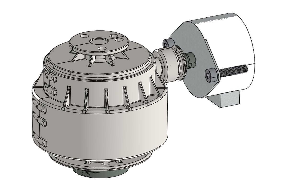
Drive enters horizontally from an offset motor mounting block, turns into the vertical axis, and is reduced through an epicyclic set housed inside the main body. The ghosted view shows the arrangement clearly: an internal ring gear around the circumference with planet gears meshing inside it. Putting the reduction on the pump's own axis keeps the drive compact and lets the output sit directly above the pump head rather than alongside it.
Why epicyclic here
An epicyclic set shares load across several planet meshes at once. For a given torque that means smaller teeth and a smaller overall diameter than a single external pair could manage, which matters when the gearbox has to sit within the footprint of the pump it drives. It also keeps input and output concentric, so the whole assembly stacks vertically without an offset jog in the middle.
Ribbing, and what it is for
The housing carries a radial array of external vertical ribs. They do two jobs: they stiffen thin cast wall sections against the ringing that a gear mesh excites, and they add surface area for heat to escape. A pump drive often runs continuously, so heat that is not shed accumulates in the oil — and hot oil thins out, which is a slow route to gear damage.
Splitting and clamping
The body is split into sections clamped by socket head cap screws through integral boss lugs. Splitting it that way means the gear set can be assembled and inspected without needing access through a single small opening, while the clamped joints still hold the bore alignment the gear mesh depends on.


What was delivered
A full 3D assembly of the drive, housing and cover drawings with the bolt-circle detail, the gear arrangement modelled as a working assembly, and mounting details for both the pump head above and the drive block alongside.
Have a similar requirement? Send the drawings, a sketch or a description — an engineer will scope it and reply with an itemised quote within one business day. Request an engineering quote.