- Client
- Fabrication company, Australia (name withheld under NDA)
- Industry
- Industrial Machinery & Presses
- Service
- Machine & Equipment Design
- Platform
- SolidWorks
- Client region
- Australia
- Arm
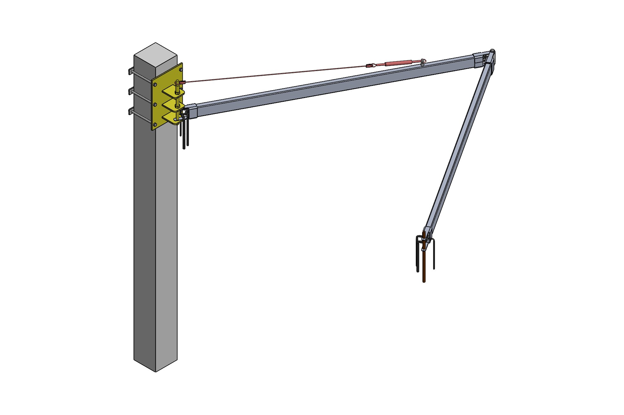
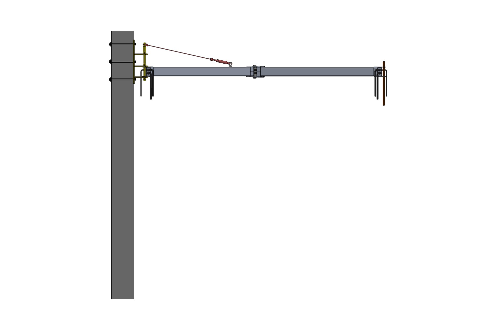
- 2 × 100 × 50 × 3 aluminium RHS · 2500 mm reach each section
- Stay
- Steel rope with turnbuckle to the wall mounting plate
- Services
- Air, power and vacuum droppers · 4 tube infills · swing mechanism at the elbow
The challenge
An arm of this reach in aluminium sags unless it is stayed, and the stay must not interfere with the swing. The services run inside the RHS, so every joint has to pass hoses and cables through while still pivoting.
The fabricator needed a design they could make from stock RHS, plate and standard pivots, with the loads at the wall fixing known so the building could be checked.
Our approach
The arm was laid out as two 100 × 50 × 3 aluminium RHS sections with a swing mechanism at the elbow and an end bracket supporting the dropper, stayed by a steel rope and turnbuckle from the wall mounting plate to the first section. Four tube infills stiffen the RHS at the pivots and fixings.
The assembly was modelled with the hoses' routing space inside the sections and the pivots detailed so the services pass through the elbow. The swing was checked through its full travel for clearance to the wall and the post, and the moment at the wall plate was calculated for the fixing design.
Two drawing sheets were issued: the wall-mounted assembly with the mounting plate, rope and turnbuckle, and the arm sections with the pipe sub-assemblies (PIPE 1, PIPE 2) and the air, power and vacuum droppers, plus a 3D PDF for the workshop.
What was delivered
The armature was fabricated from the two-sheet drawing set and installed in the bay. The design has since been reused for a second bay with a shorter reach from the same model.
- SolidWorks assembly with pipe sub-assemblies
- 2-sheet fabrication drawing set
- Wall fixing load summary
- 3D PDF for the workshop
- STEP files
Standards and conventions applied
- Fabricator tolerance table and A3 template
- AS 1100 drawing practice
- AS/NZS 1664 aluminium structures reference for the stayed arm
Have a similar requirement? Send the drawings, a sketch or a description — an engineer will scope it and reply with an itemised quote within one business day. Request an engineering quote.