- Client
- Electric drivetrain developer, United Kingdom (name withheld under NDA)
- Industry
- Industrial Machinery & Presses
- Service
- Machine & Equipment Design
- Platform
- SolidWorks
- Client region
- United Kingdom
- Motor
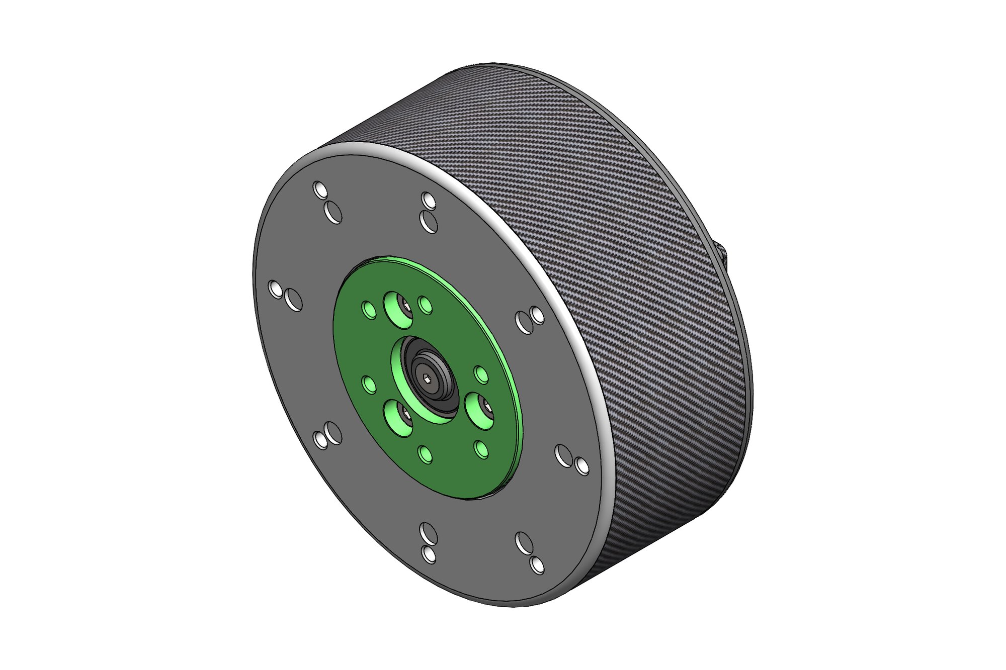
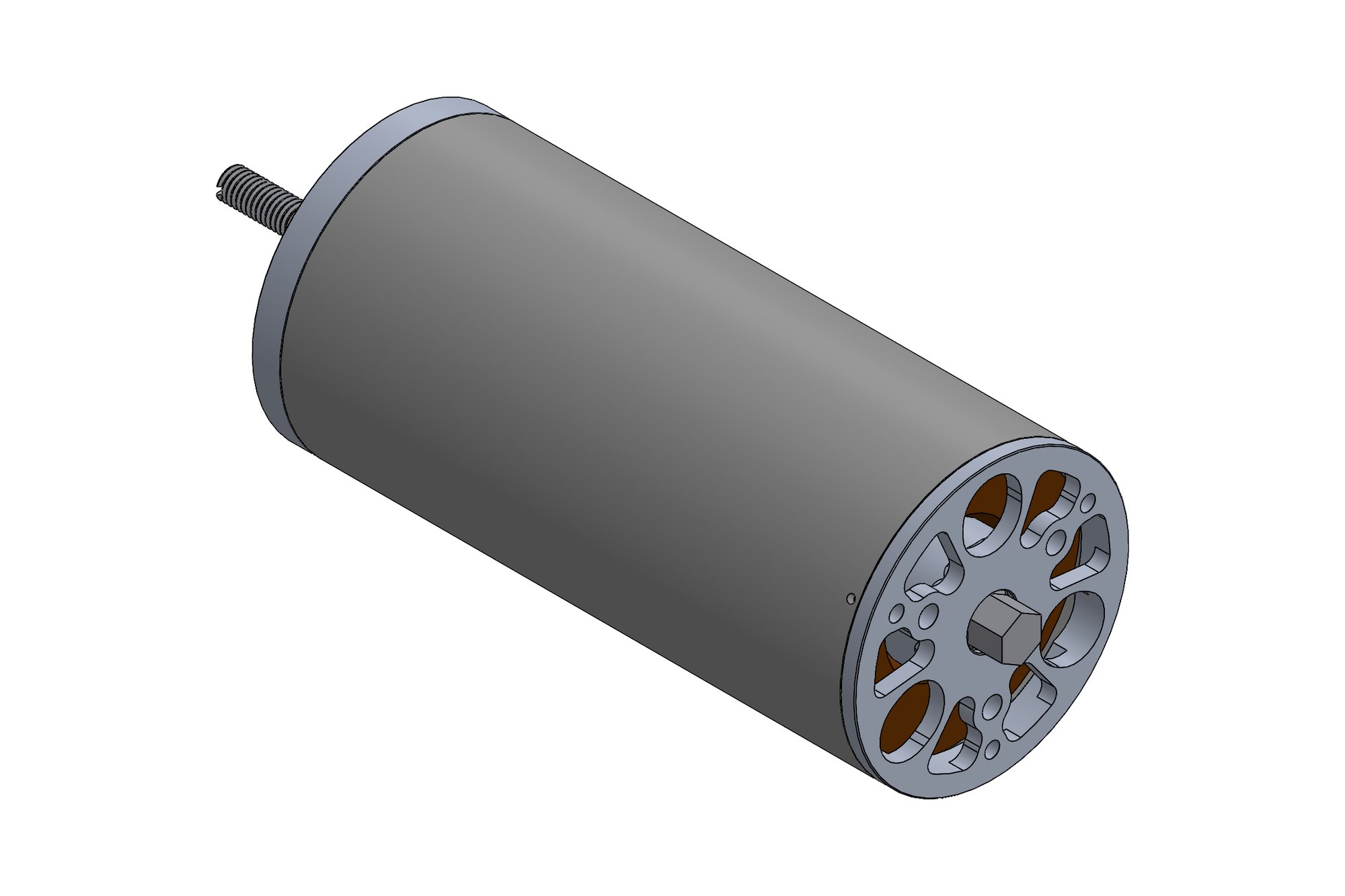
- Stator stack · SmCo magnets · Inconel rotor sleeve · front/rear end frames
- Rig
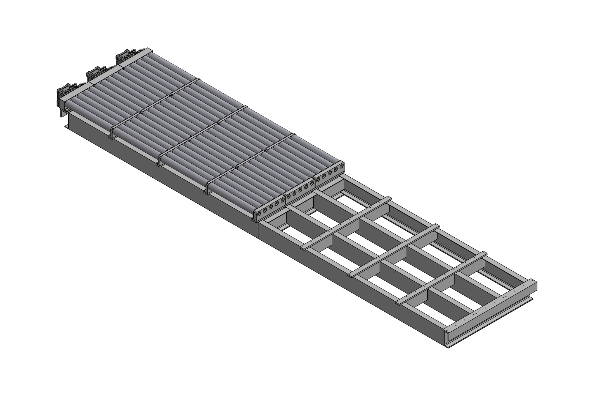
- Adjustable alignment base · rigid and lateral bases · blast case · guide rods
- Package
- 138 parts · 26 drawings on the client's A3 template
The challenge
High-speed rotors are retained by a sleeve rather than by the magnets themselves, and the sleeve material, interference and wall thickness decide whether the rotor survives. The motor had to be designed so that the magnets, the Inconel sleeve and the shaft could be assembled in a defined order and the stator stack located to the same datums as the end frames.
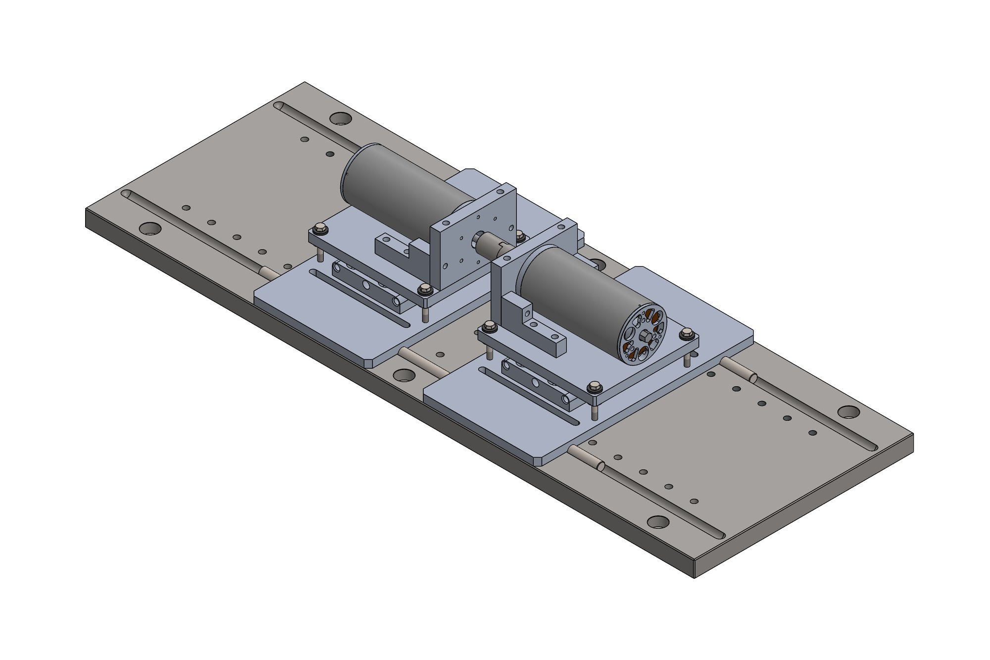
The rig then had to hold that motor and its load unit in alignment, allow the alignment to be adjusted after each build, contain a failure, and still be simple enough for a small workshop to make from plate and standard parts.
Our approach
The motor assembly was modelled as a rotor sub-assembly (shaft, magnet set, Inconel sleeve) and a wound stator sub-assembly inside a housing, with the front and rear end frames carrying the bearings. Every mating face was dimensioned to a common datum so the airgap is set by machining, not by assembly skill.
For the rig we designed an adjustable alignment base in three parts, a rigid base for the load side, a lateral base, and a coupling pair with M6 left-hand threaded faces and 10 H7 dowels so the two halves can only go together one way. The blast case, disc, guide rods, support and front frame were detailed as plate parts with every hole positioned to the bed-plate grid, together with mounting and coupling plates for the existing motion rig.
All 26 drawings were produced on the client's own template and numbering so they slot into their drawing register, and the whole rig was issued as a SolidWorks assembly they can modify for the next motor variant.
What was delivered
The client received a 138-part SolidWorks assembly, 26 manufacturing drawings and STEP files. The rig was built from the first issue and the motor assembly drawings are now their reference set for the following motor sizes.
- SolidWorks rig and motor assemblies (138 parts)
- 26 part and assembly drawings on client template
- Rotor and stator sub-assembly drawings with assembly sequence
- Coupling, base and blast-case plate drawings
- STEP files for machining
Standards and conventions applied
- ASME Y14.5 dimensioning on client template
- ISO 286 fits on couplings and dowels (H7)
- Client drawing numbering and revision control
Have a similar requirement? Send the drawings, a sketch or a description — an engineer will scope it and reply with an itemised quote within one business day. Request an engineering quote.