- Client
- Electric drivetrain developer, United Kingdom (name withheld under NDA)
- Industry
- Industrial Machinery & Presses
- Service
- Product Design & Development
- Platform
- SolidWorks
- Client region
- United Kingdom
- Gearing
- Single-stage planetary · ring gear 92.75 mm PCD · 3 planets
- Electronics
- Hall-effect PCB · comms PCB · rear PCB cover and screen
- Package
- MK1–MK3 iterations · 89 drawings · ring, planet, sun, carrier and rotor details
The challenge
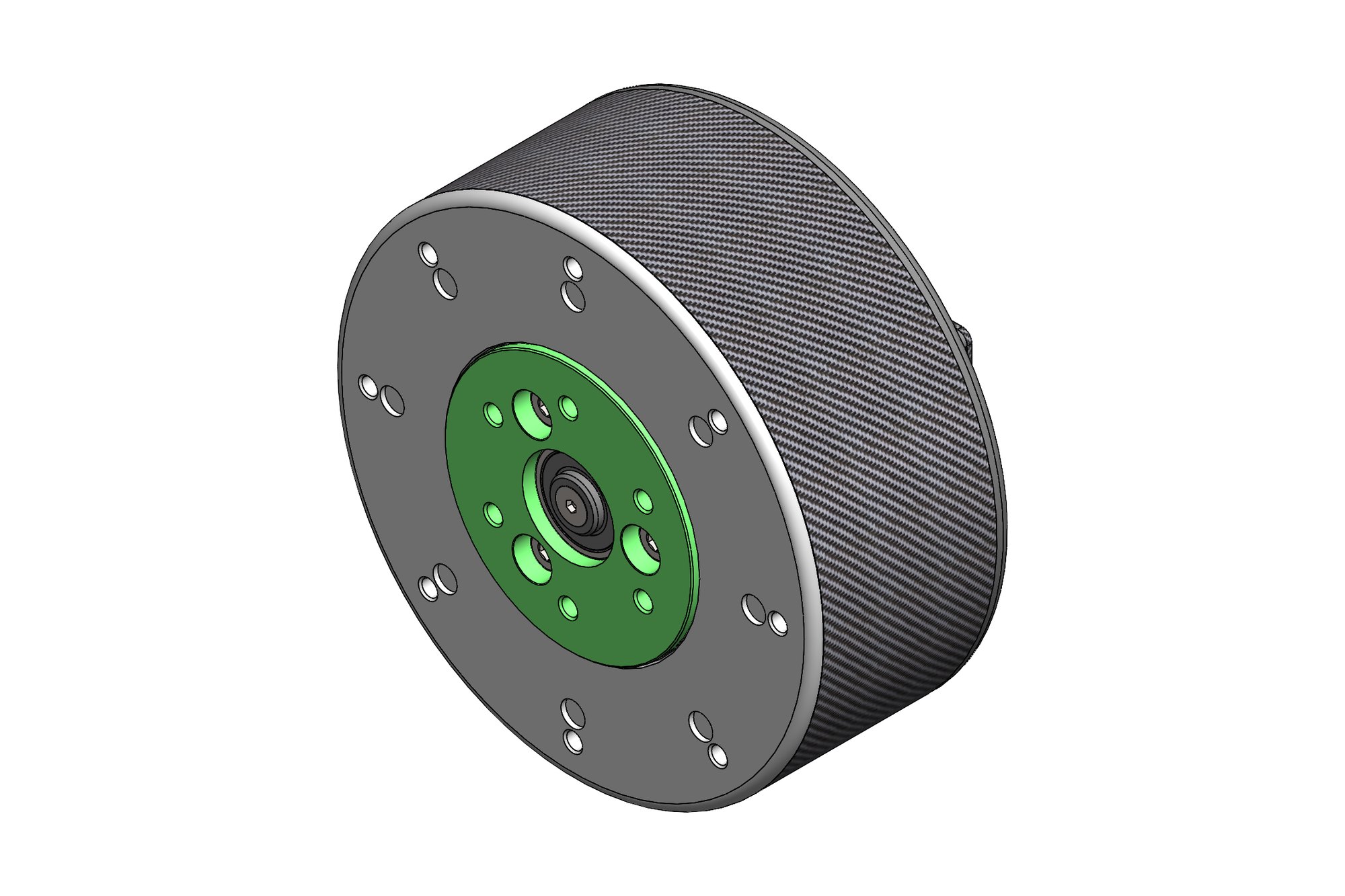
The actuator has to fit a fixed diameter and length set by the leg geometry, deliver its torque through a single planetary stage, and carry the rotor position sensor and communications board inside the same housing. Planet gears at this size run at 14 mm diameter with profile tolerances of a few microns, and the carrier plate must hold the planet pins within 0.02 mm to share load evenly.
Three marks were needed because the electrical and mechanical designs moved together: a change to the magnet holder or the PCB outline changed the rear cover, the outer tube and the thermal path.
Our approach
The gear set was designed first — ring gear on a 92.75 mm PCD with the fixing pattern on a 55 mm PCD, sun gear and planet gears with 0.002 mm profile tolerance callouts, planet pins and thrust washers — and checked for the planetary assembly condition and for backlash at the output. The carrier and carrier plate were detailed with the pin bores toleranced to datum B.
The rotor, armature retaining plate, SRD magnet holder and outer tube were developed with the client's electrical team; the outer tube was issued in two variants (aluminium and composite) with the same interfaces. The Hall-effect PCB, communications PCB, rear PCB cover and rear screen were modelled from the board outlines with protected areas marked so the mechanical parts never encroach on the components.
Every part was drawn on the client's A3 template with their numbering (10002113 to 10002207 series), including the slot cutter needed to make the rotor, so the whole actuator can be manufactured and assembled from the drawing set alone.
What was delivered
The MK3 actuator is fully documented: 89 drawings, the SolidWorks assembly with all three marks preserved, and a parts list that separates machined, moulded, wound and bought-out items. The client uses it as the base design for the other joints of the robot.
- SolidWorks actuator assembly (MK1, MK2, MK3)
- 89 part drawings on client template
- Ring, planet and sun gear drawings with profile tolerances
- PCB envelope models with protected areas
- Tooling drawing for the rotor slot cutter
Standards and conventions applied
- ASME Y14.5 geometric tolerancing on client template
- ISO 1328 gear accuracy on planetary parts
- Client numbering and change-note revision control
Have a similar requirement? Send the drawings, a sketch or a description — an engineer will scope it and reply with an itemised quote within one business day. Request an engineering quote.