- Client
- Industrial gearbox builder, Gujarat (name withheld under NDA)
- Industry
- Industrial Machinery & Presses
- Service
- Machine & Equipment Design
- Platform
- SolidWorks
- Client region
- India
- Frame
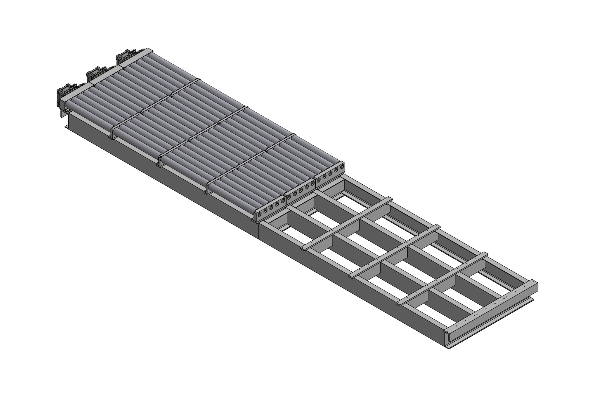
- 8231 mm fabricated channel frame in two sections with connecting plates
- Drive
- Worm gear unit size 110 · 2.2 kW 112M motor · 20T/21T × 4 M gear shafts
- Variants
- 4 stacker builds · 35–54 parts each · 14 drawings per build
The challenge
The customer builds drives and had been asked to supply the complete stacker, frame included. Four units were needed in quick succession, each slightly different: frame length, number of rollers, drive side and the bracket that carries the worm gear unit. Drawing each one from scratch would have taken longer than the fabrication.
The gear shafts that drive the rollers are precision parts — 20T and 21T × 4 module, ground, carburised to 58–62 HRC, DIN 7 accuracy — sitting in a frame built to fabrication tolerances. The design had to bridge that gap with machined brackets and adjustable mountings so the shop could weld the frame first and align the drive afterwards.
Our approach
The first stacker was built as a configurable SolidWorks assembly: frame sections, connecting plate, roller count and drive position are driven by a handful of dimensions. The three later variants were produced by changing those values and re-issuing the drawings, which kept all four builds consistent and cut the drawing time for each new order to a day.
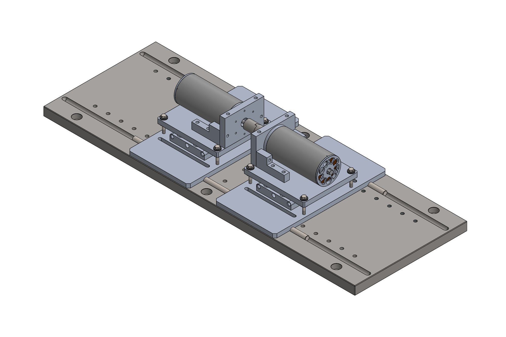
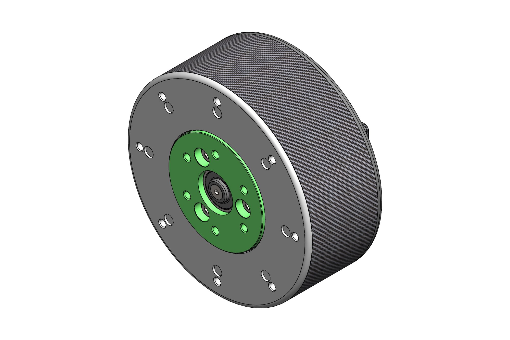
The frame is two fabricated channel sections joined by a connecting plate, 8231 mm overall, with the roller bed and feed roller assemblies mounted on machined pads. The drive is a right-angle worm gear unit (size 110, 2.2 kW, 112M motor frame) on a four-part machined mounting bracket with a 165 mm PCD, eight 14 mm holes and a 130 H7 spigot so the gear unit locates positively and can be swapped in service.
Every build was issued with a frame assembly drawing, part drawings for the brackets, covers, connecting plate and gear shafts (with full gear data), and a GA showing the worm gear unit and motor from the supplier catalogue data the customer had chosen.
What was delivered
Four complete stacker packages — 14 drawings each — delivered over the course of the year from one master model. The customer fabricated the frames and machined the brackets in-house and fitted the standard worm gear units without rework.
- Configurable SolidWorks stacker assembly
- Frame assembly and fabrication drawings for 4 variants
- Gear shaft drawings with gear data and heat-treatment notes
- Machined bracket, cover and connecting plate drawings
- GA with worm gear unit and motor interface
Standards and conventions applied
- ISO 2768 general tolerances on fabrications
- ISO 286 fits on bracket spigots and shafts
- DIN 3962 gear accuracy on gear shafts
- Customer title block and critical-parameter marking
Have a similar requirement? Send the drawings, a sketch or a description — an engineer will scope it and reply with an itemised quote within one business day. Request an engineering quote.