- Client
- Extruder gearbox manufacturer, Ahmedabad (name withheld under NDA)
- Industry
- Gearboxes & Power Transmission
- Service
- 3D Modelling & 2D Drafting
- Platform
- Solid Edge, AutoCAD
- Client region
- India
- Range
- Single-screw PBH 125–250 · twin-screw 110–370 frames
- Platform
- Solid Edge ordered modelling
- Output
- Sectional GAs, machining drawings, pattern drawings
The challenge
The manufacturer had decades of 2D drawings and a few partial 3D models across several frame sizes. New orders meant redrawing details by hand, and a design change on one frame was not reflected on the others. They wanted a consistent 3D library in Solid Edge — their chosen platform — that their own drawing office could maintain.
Twin-screw units add a torque-splitting stage: the input torque is divided between two output shafts whose centre distance is fixed by the screw geometry of the extruder, often too small for a conventional gear pair. The thrust pack — a stack of tandem thrust bearings behind each output shaft — has to absorb the full screw thrust and must be detailed so it can be assembled and shimmed on the bench.
Our approach
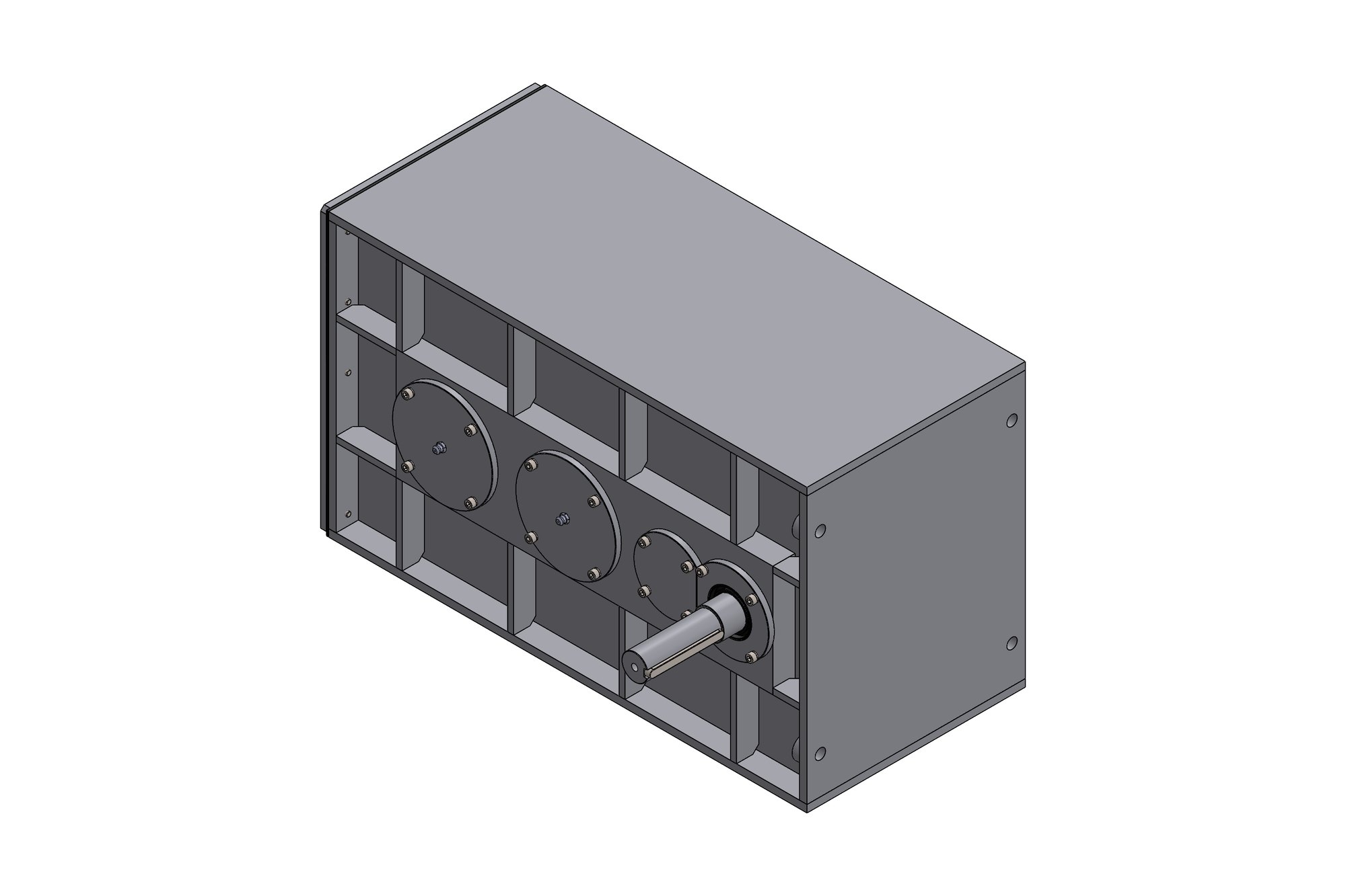
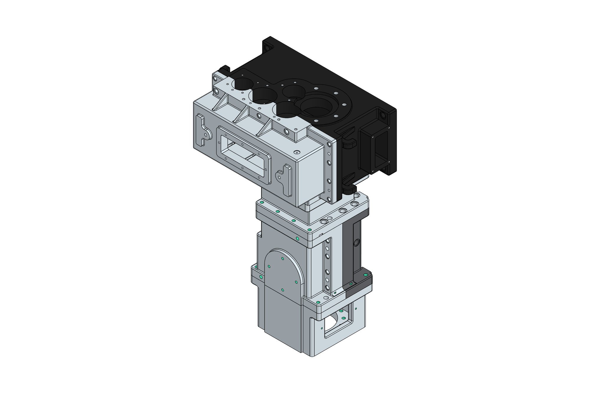
Each frame size was modelled as an ordered Solid Edge assembly with the gear train, shafts, bearings, thrust pack, housing halves and covers as separate parts, using a shared naming convention so parts common to several frames are reused rather than copied. Existing 2D data was imported and used as the base for sketches, so the new models agreed with the parts already in the field.
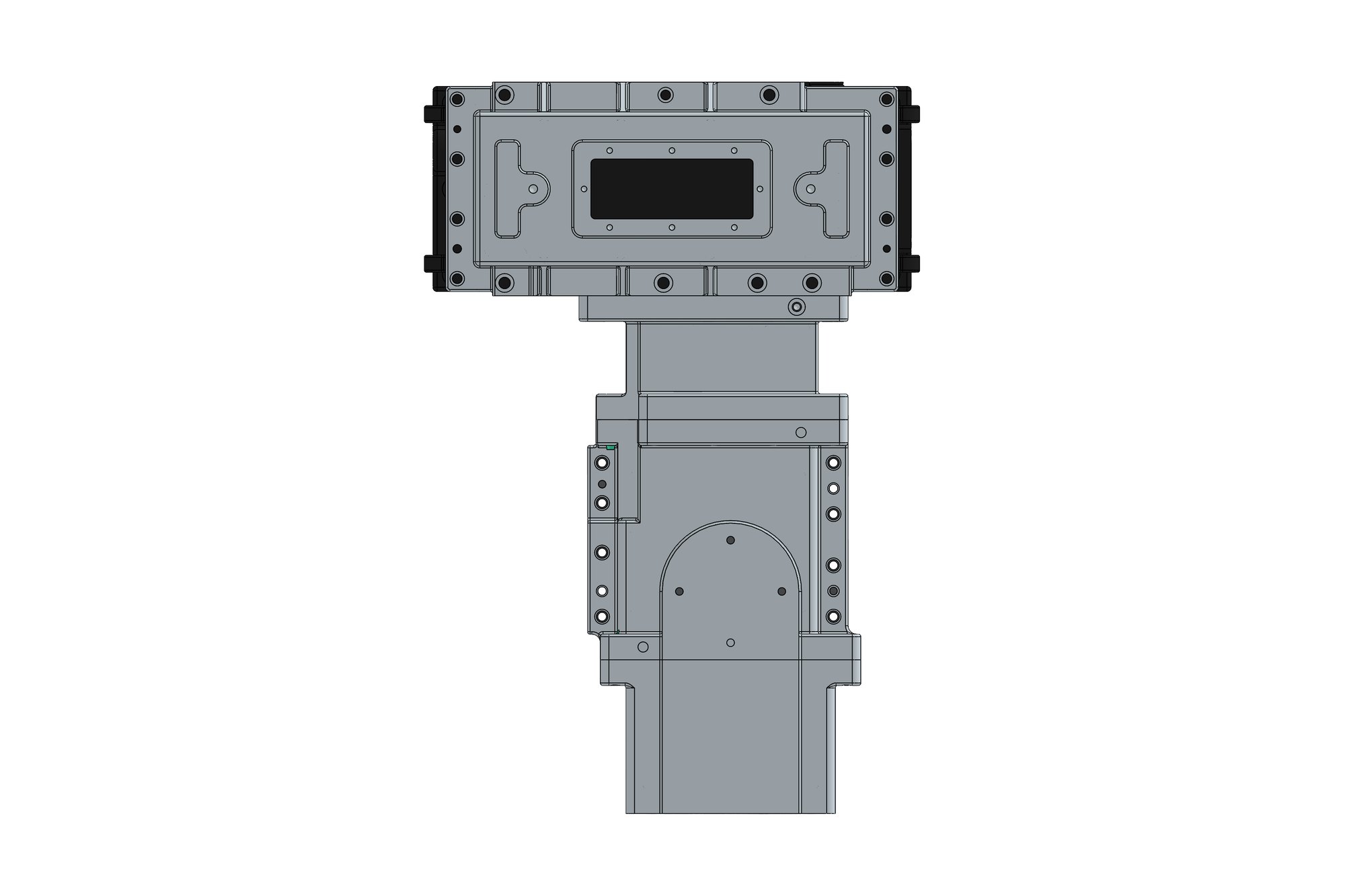
Housings were modelled with the real machining sequence in mind: bearing bores on a common axis for line boring, split-line faces machined together and dowelled, and lifting lugs and oil fittings in the positions the shop already used. Pattern drawings for the cast housings were produced from the same models with draft and allowances.
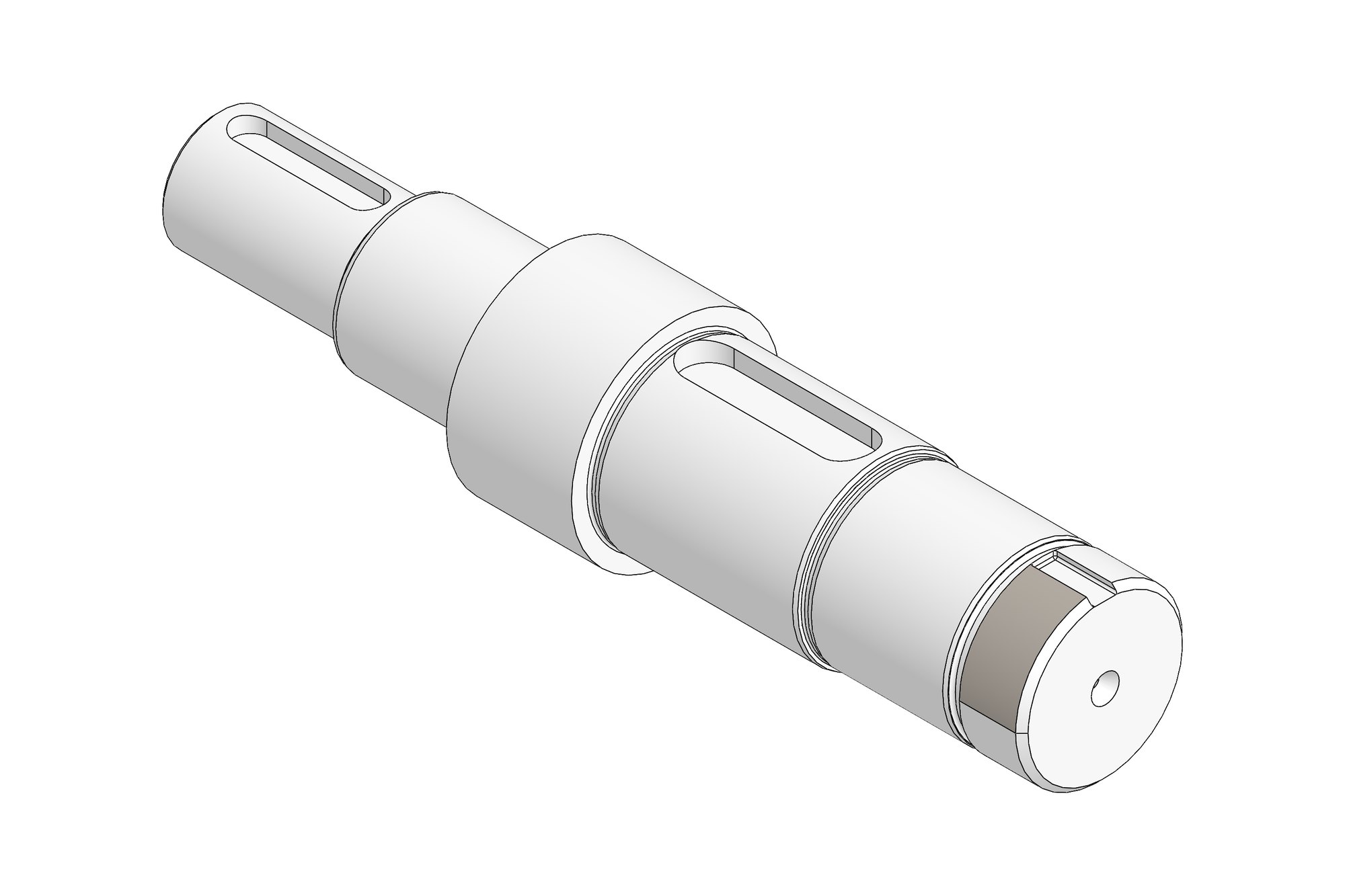
Sectional GA drawings were produced for every frame showing the gear train, bearing arrangement and thrust pack with shim thicknesses tabulated, so assembly fitters work from one sheet. Machining drawings for gears, shafts and housings followed the customer's existing title block and tolerance table.
What was delivered
The manufacturer now holds a Solid Edge library covering their single-screw and twin-screw ranges, with GA, machining and pattern drawings generated from the models. New frame variants are derived from the nearest existing frame instead of being drawn from scratch, and spares drawings for older gearboxes in the field are produced from the same data.
- Solid Edge assemblies per frame size (PAR/ASM/DFT)
- Sectional GA drawings with shim and bearing tables
- Gear, shaft and housing machining drawings
- Casting pattern drawings
- Parasolid and STEP exports for suppliers
Standards and conventions applied
- Customer drawing template and general tolerance table
- ISO 2768 general tolerances on legacy-compatible drawings
- Gear data tables for hobbing and grinding
Have a similar requirement? Send the drawings, a sketch or a description — an engineer will scope it and reply with an itemised quote within one business day. Request an engineering quote.