- Client
- Steel fabrication contractor, Gujarat (name withheld under NDA)
- Industry
- Sheet Metal & Steel Fabrication
- Service
- Structural Steel Detailing
- Platform
- SolidWorks
- Client region
- India
- Size
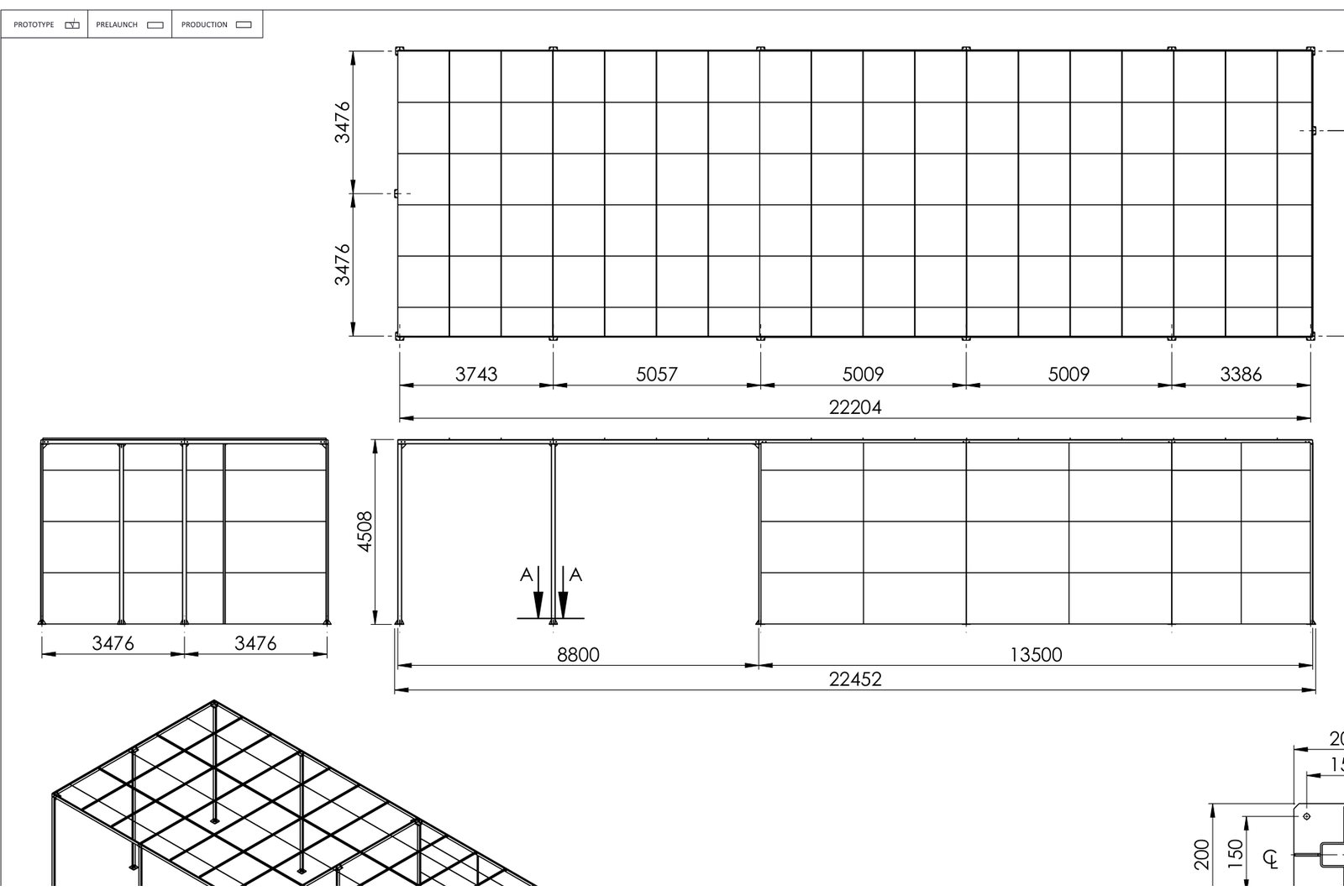
- 13,500 × 7,000 × 4,500 mm
- Foundation
- Base plates with 4 × Ø11 holes for M10 anchors
- Outputs
- GA drawing, 3D PDF, STEP, member cut list
The challenge
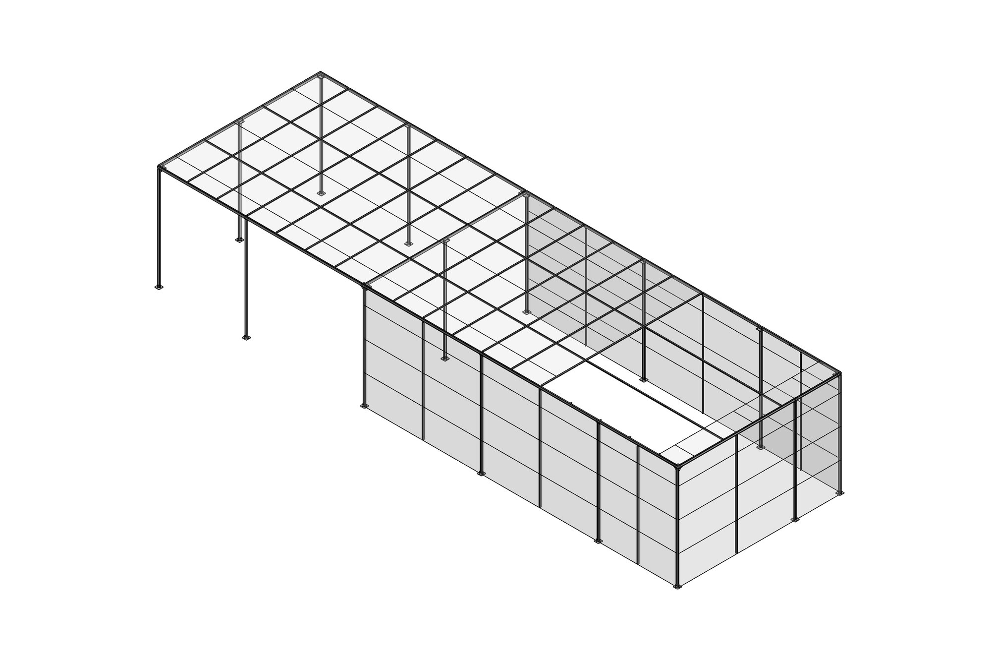
The contractor had a site sketch with overall sizes and a column grid, and needed to order steel and set out foundations quickly. The model had to produce a member schedule, show the foundation plate positions and anchor holes, and give the site team a 3D view they could open without CAD.
Our approach
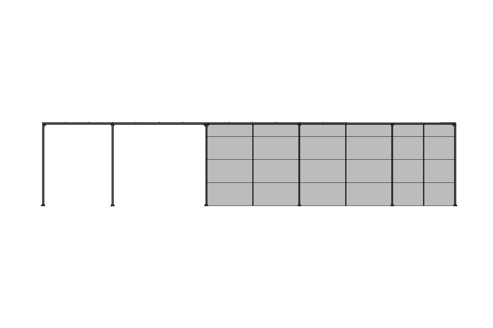
The structure was modelled as a SolidWorks weldment using standard sections for the columns, rafters, purlins and bracing, with the clad enclosure panels as sheet-metal parts on the end bays. Base plates with their anchor-hole patterns were modelled and dimensioned in a foundation section on the GA drawing, with critical set-out dimensions marked.
The weldment cut list gave the member schedule directly; the GA drawing carried plan, elevations and the foundation plate section; and a 3D PDF was issued alongside STEP so the site team and the client could review the structure on any PC.
What was delivered
The contractor ordered steel from the cut list and set out the foundations from the GA within the week, and reused the model to quote a longer variant of the same shed.
- SolidWorks weldment model of the structure
- GA drawing with foundation plate section
- Member cut list
- 3D PDF and STEP
Standards and conventions applied
- IS 800 / general structural detailing conventions
- Critical-parameter marking on set-out dimensions
- ISO 2553 weld symbols
Have a similar requirement? Send the drawings, a sketch or a description — an engineer will scope it and reply with an itemised quote within one business day. Request an engineering quote.