- Client
- Fabrication company, Australia (name withheld under NDA)
- Industry
- Sheet Metal & Steel Fabrication
- Service
- Sheet Metal & Fabrication
- Platform
- SolidWorks
- Client region
- Australia
- Material
- 1.5 mm 304 stainless · No. 4 brushed finish · grain direction marked
- Panels
- 1158 × 901 · 1196 × 901 · 1487 × 443 · 547 × 443 · 417 × 778 (1, 2 and 4 off)
- Package
- 94 parts in 45 assemblies · 13 flat-pattern drawings · R1.5 returns
The challenge
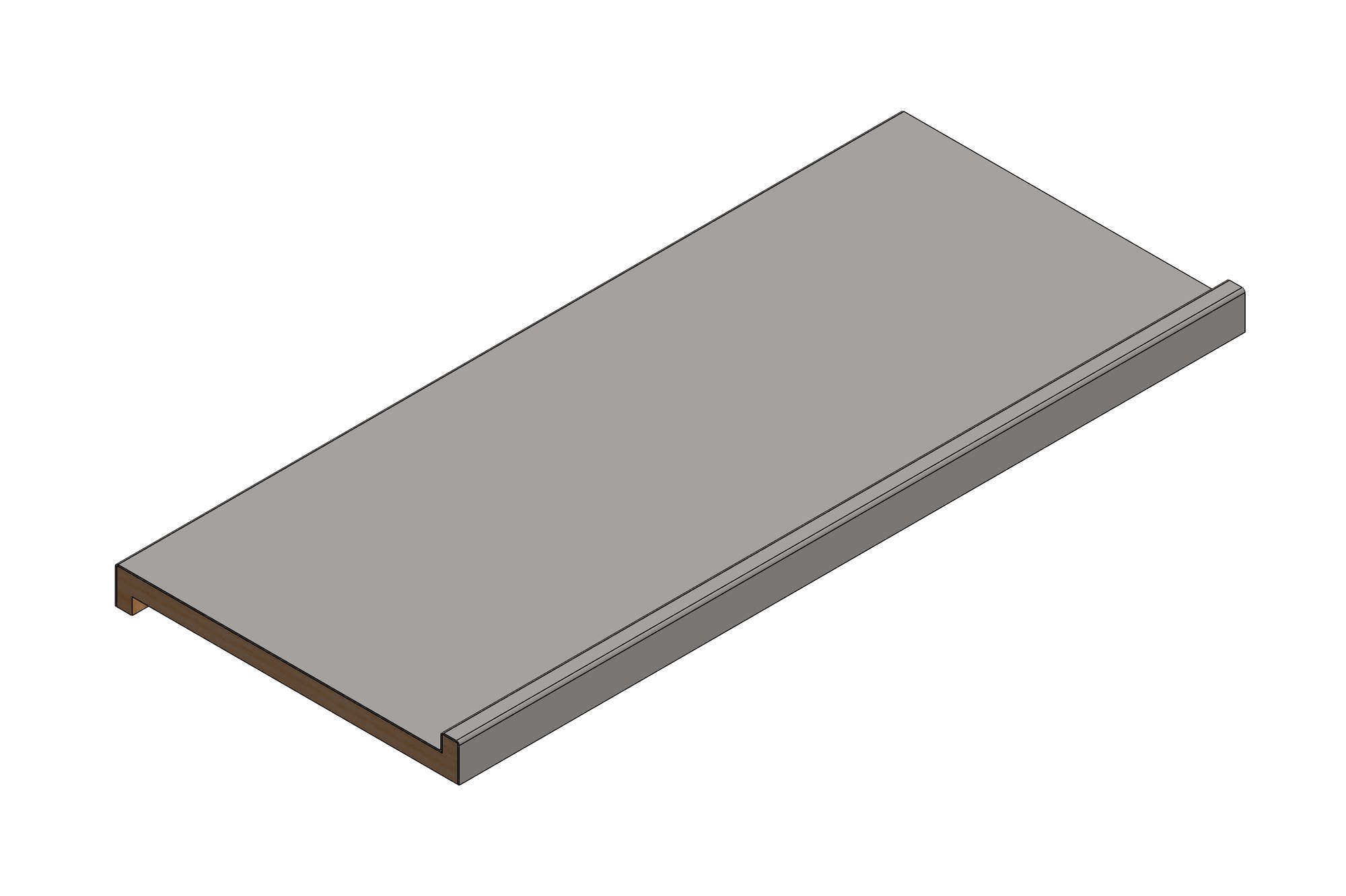
The brief was an engineering spreadsheet of panel positions and sizes plus photographs of the wall. Each position needed a folded panel with returns that overlap the neighbours by a fixed amount, and the panels came in one-, two- and four-off quantities with small size differences that are easy to confuse in the shop.
No. 4 finish has a visible grain. The flat pattern for each panel had to be drawn with the grain direction shown so the panels were cut from the sheet the right way round and folded without scoring the face.
Our approach
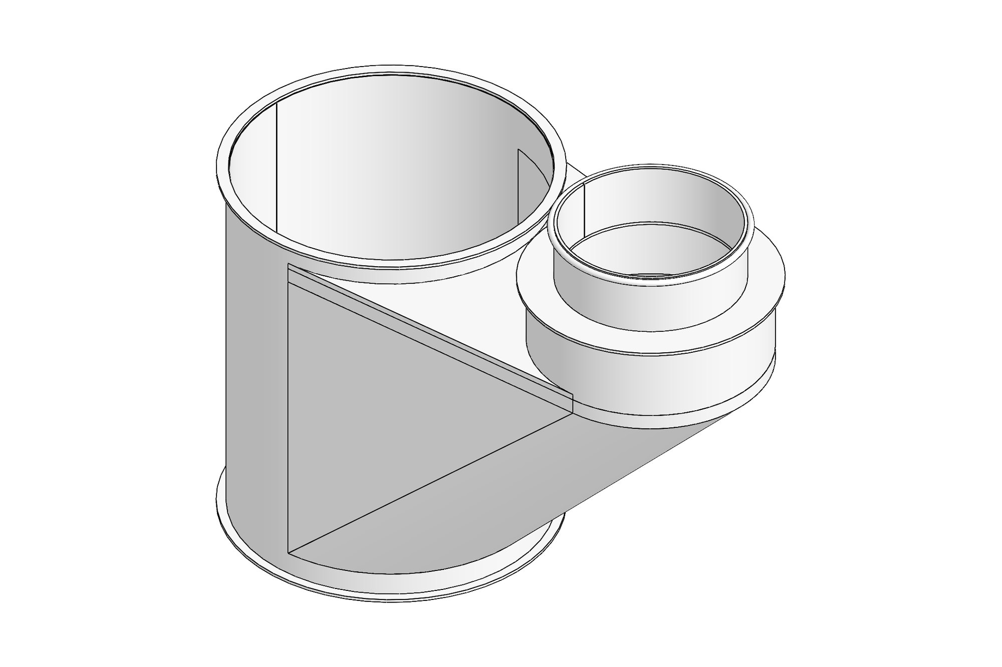
Every panel was modelled as a 1.5 mm sheet-metal part with 17 mm returns at R1.5, then grouped into assemblies by quantity (1-off, 2-off and 4-off families) so the drawing set mirrors the delivery schedule. Flat patterns were generated from the models with the overall flat size — for example 1192 × 901 for the 1158 × 901 finished panel — and the grain direction marked on the pattern.
A revision 2 model set was produced after the first site check adjusted the returns on the 12 mm reveal panels, keeping both revisions as separate assemblies.
Thirteen flat-pattern drawings were issued on the fabricator's A3 template with material, finish and grain noted on each, together with the DXF profiles for cutting.
What was delivered
The fabricator cut and folded all panel sizes from the flat patterns with the grain consistent across the wall, and the second-revision panels fitted the reveals without site trimming.
- SolidWorks sheet-metal models grouped by quantity (94 parts)
- 13 flat-pattern drawings with grain direction
- DXF profiles for laser cutting
- Revision 2 model set after site check
- Panel schedule matching the engineering brief
Standards and conventions applied
- Fabricator tolerance table and A3 template
- AS 1100 drawing practice
- Sheet-metal K-factor and bend table for 1.5 mm 304
Have a similar requirement? Send the drawings, a sketch or a description — an engineer will scope it and reply with an itemised quote within one business day. Request an engineering quote.