- Client
- Fabrication company, Australia (name withheld under NDA)
- Industry
- Sheet Metal & Steel Fabrication
- Service
- Sheet Metal & Fabrication
- Platform
- SolidWorks
- Client region
- Australia
- Unit 1
- 3000 mm top · 695 mm drum bases · 4 pigeon holes · 250 mm under-structure
- Unit 2
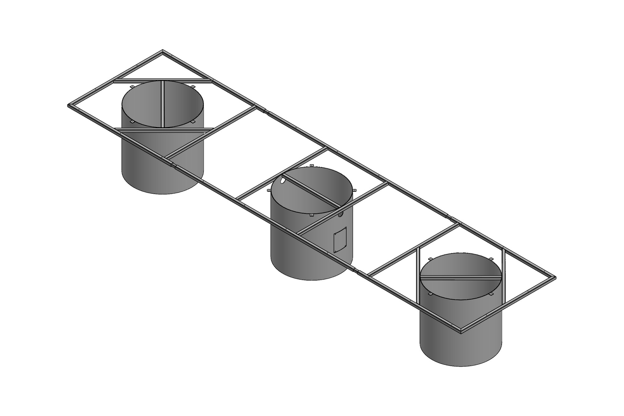
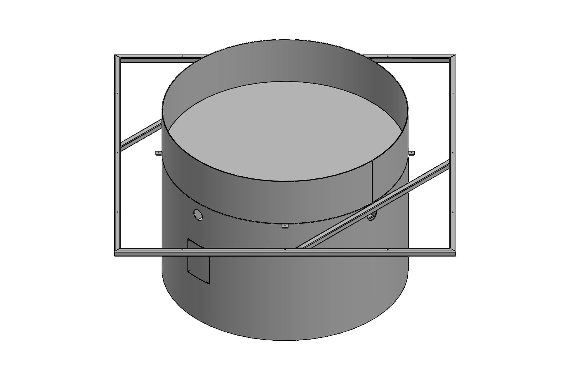
- 1200 mm dia planter with drip tray · 5400 × 1800 framed base
- Frames
- 50 × 50 × 3 angle · 2532 mm · 36° gusset cuts · satin powder-coat finishes
The challenge
The input was intentional but informal: a one-page layout with overall sizes, hatched areas for the drums, pigeon-hole positions marked in red and finish codes for two colours. Everything structural — how the drums carry the top, how the frame ties the drums together, where the under-structure sits — was ours to decide.
Both units are visible furniture, so the frames had to be hidden inside the drums and under the top, and the powder-coat colour split between the two units had to be carried through to the parts list so the coater received the right parts in the right colour.
Our approach
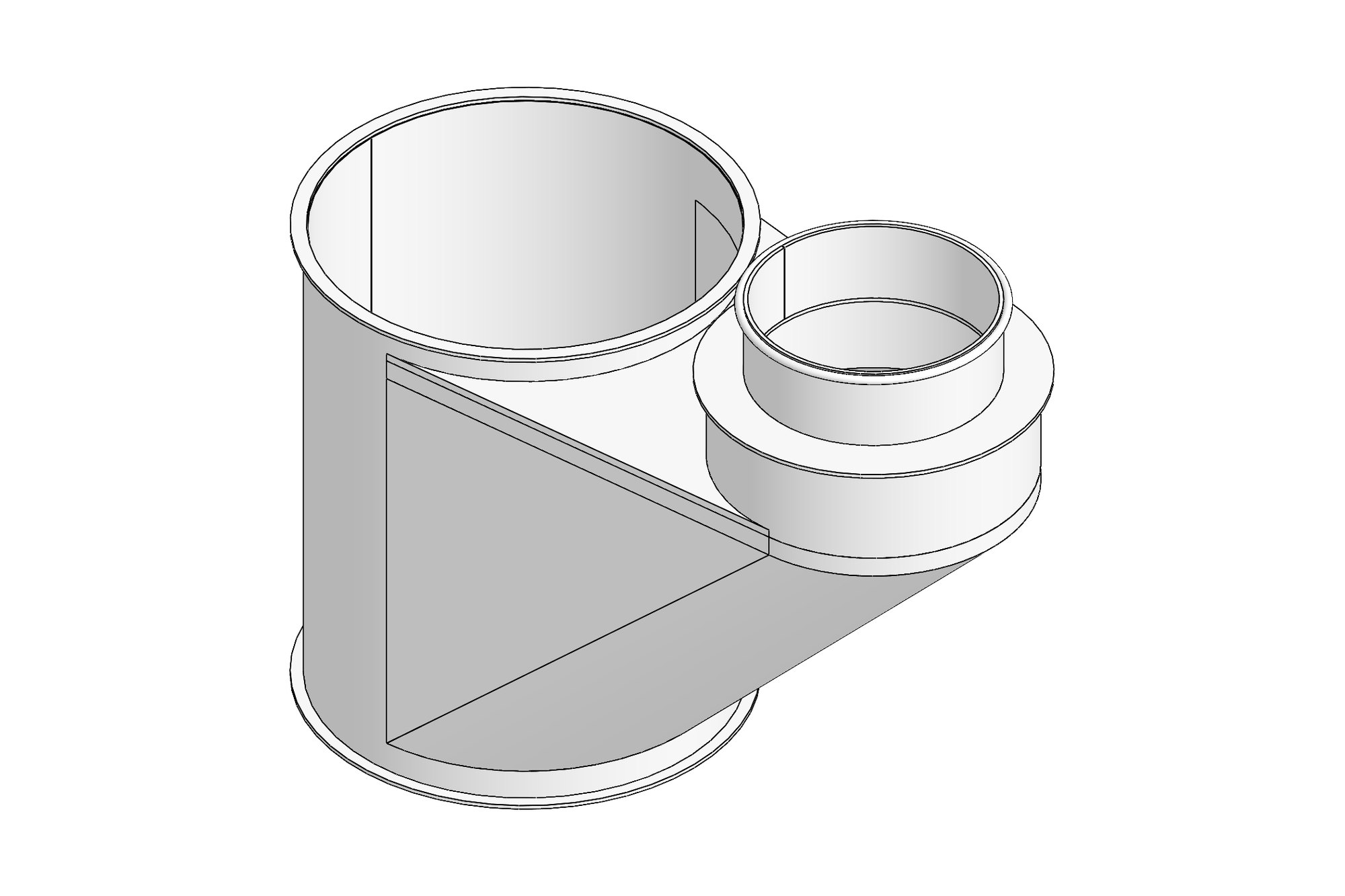
Unit TB03 was modelled as a 50 × 50 × 3 angle sub-frame 2532 mm long with 36° gusset cuts, carrying three rolled 695 mm drums and the 3000 mm top, with the four pigeon holes and the indesk box placed at the positions on the layout. Unit WS04 is a 1200 mm planter drum with a drip tray inside a 5400 × 1800 framed base, keeping the 250 mm under-structure clear.
Each unit was issued as an assembly drawing with the drum, angle and top as separate part drawings, and the two finish codes (satin powder-coat in two colours) called out per part so the coating shop could sort them.
A first revision went back to the designer with the drum positions dimensioned; the r1 issue incorporated their adjustments and was released to the shop.
What was delivered
Fabrication drawings for both units — drums, angle frames, tops and the planter tray — with finish codes per part and a revision trail back to the designer's layout. The fabricator built and coated both units from the r1 issue.
- SolidWorks assemblies for TB03 and WS04
- Assembly and part drawings (drums, angle frames, tops, tray)
- Finish schedule per part
- STEP files
- Revision r1 incorporating designer feedback
Standards and conventions applied
- Fabricator tolerance table and A3 template
- AS 1100 drawing practice
- Powder-coat finish codes per part on the parts list
Have a similar requirement? Send the drawings, a sketch or a description — an engineer will scope it and reply with an itemised quote within one business day. Request an engineering quote.