- Client
- Gearbox manufacturer, Gujarat (name withheld under NDA)
- Industry
- Gearboxes & Power Transmission
- Service
- Machine & Equipment Design
- Platform
- SolidWorks
- Client region
- India
- Ring gears
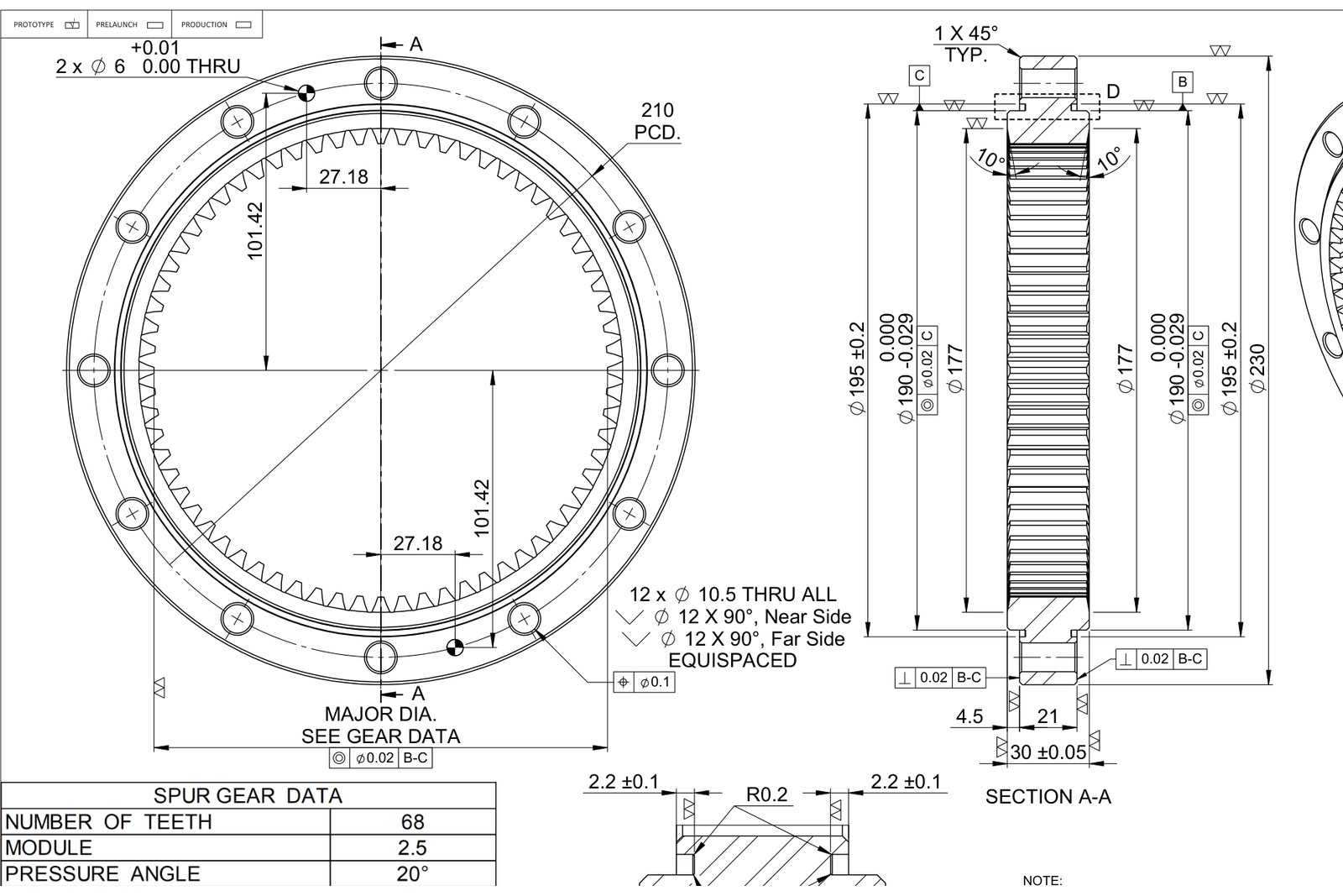
- 68T × 2.5 M · 63T × 1.8 M
- Heat treatment
- Carburised, case 1.0–1.3 mm, 58–62 HRC
- Castings
- Motor flange, 2 intermediate flanges, cover
The challenge
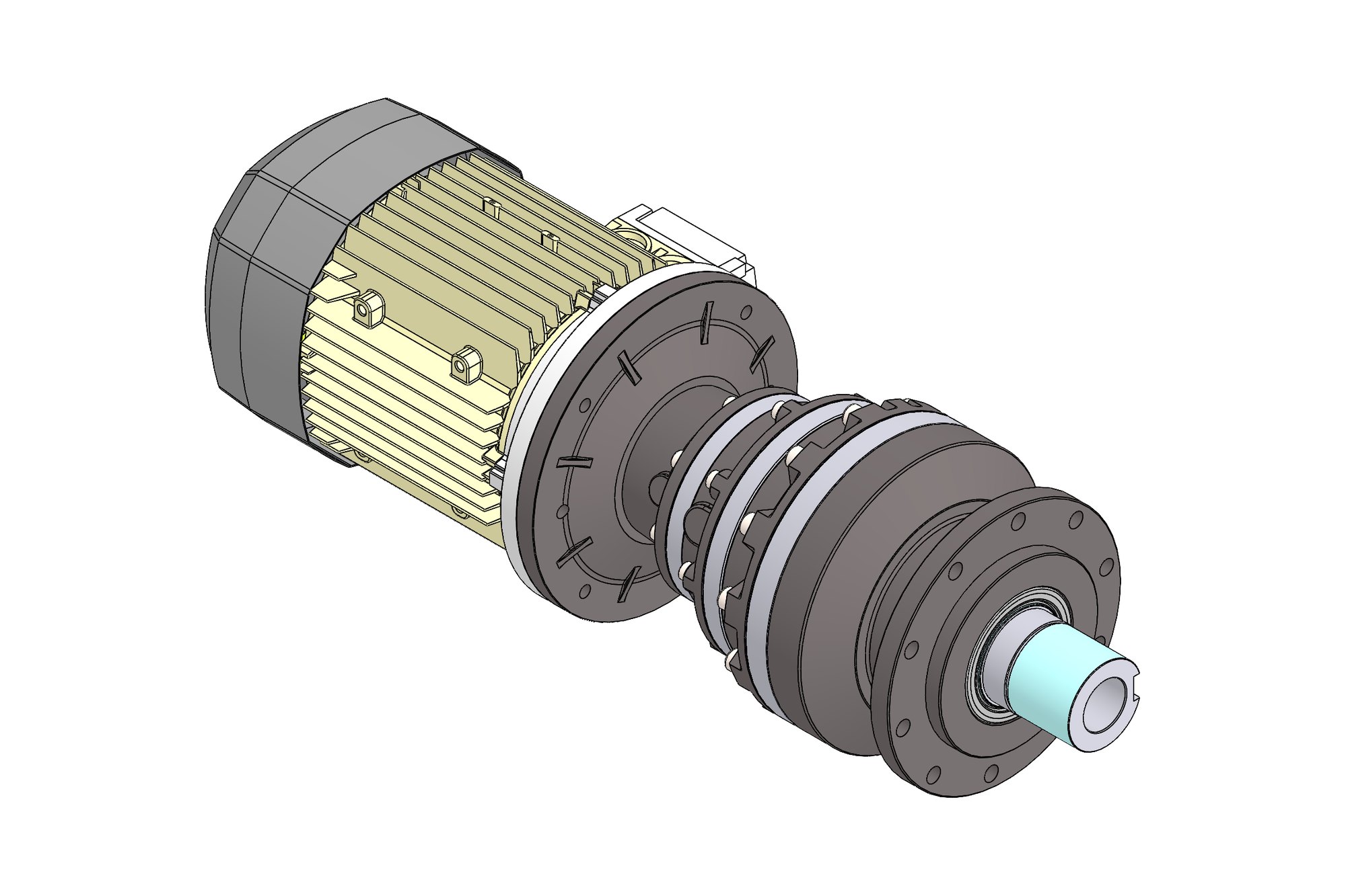
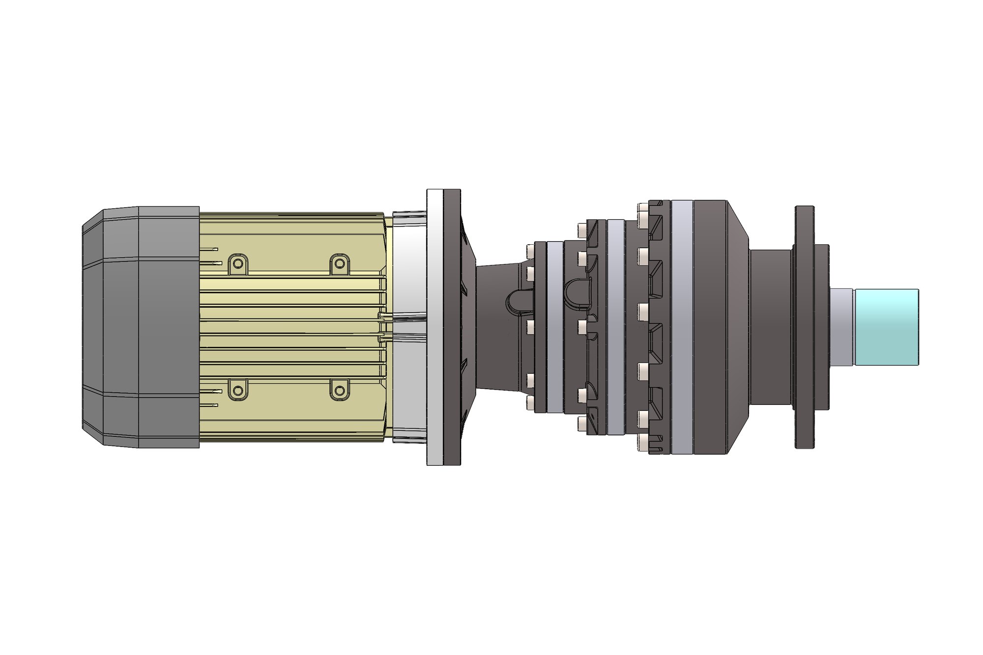
The customer builds compact geared motors and wanted a two-stage planetary unit that bolted directly to a standard motor flange. Planetary stages are unforgiving: the sun, three planets and the ring gear must share load evenly, which means the tooth counts have to satisfy the assembly condition, the carrier must hold the planet pins to a tight positional tolerance, and the ring gear must be hardened without distorting.
The housing parts were to be cast. A machined-part drawing is not enough for a foundry — they need the casting shape with draft angles, machining allowance and the parting line, and they need it as a separate model so the pattern can be made.
Our approach
Both stages were sized with a planetary gear-pair calculation covering sun, planet and ring gear materials, service life and the contact and bending safety factors, which fixed the modules at 2.5 and 1.8 mm and the ring gear tooth counts at 68 and 63. Tooth counts were checked against the planet assembly condition so three equally spaced planets mesh without interference.
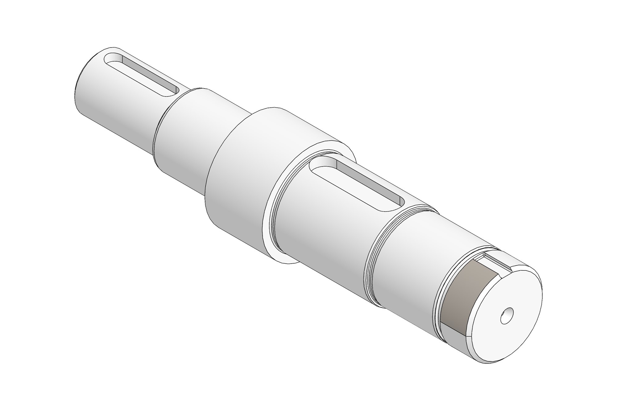
The ring gears were detailed with the 12-hole bolt pattern, a 210 mm PCD, datum structure B–C on the bores and 0.02 mm runout control on the gear faces, plus the heat-treatment note — carburise to 1.0–1.3 mm effective case depth, harden and temper to 58–62 HRC case, 33–45 HRC core — so the hardener and the grinder work to the same sheet.
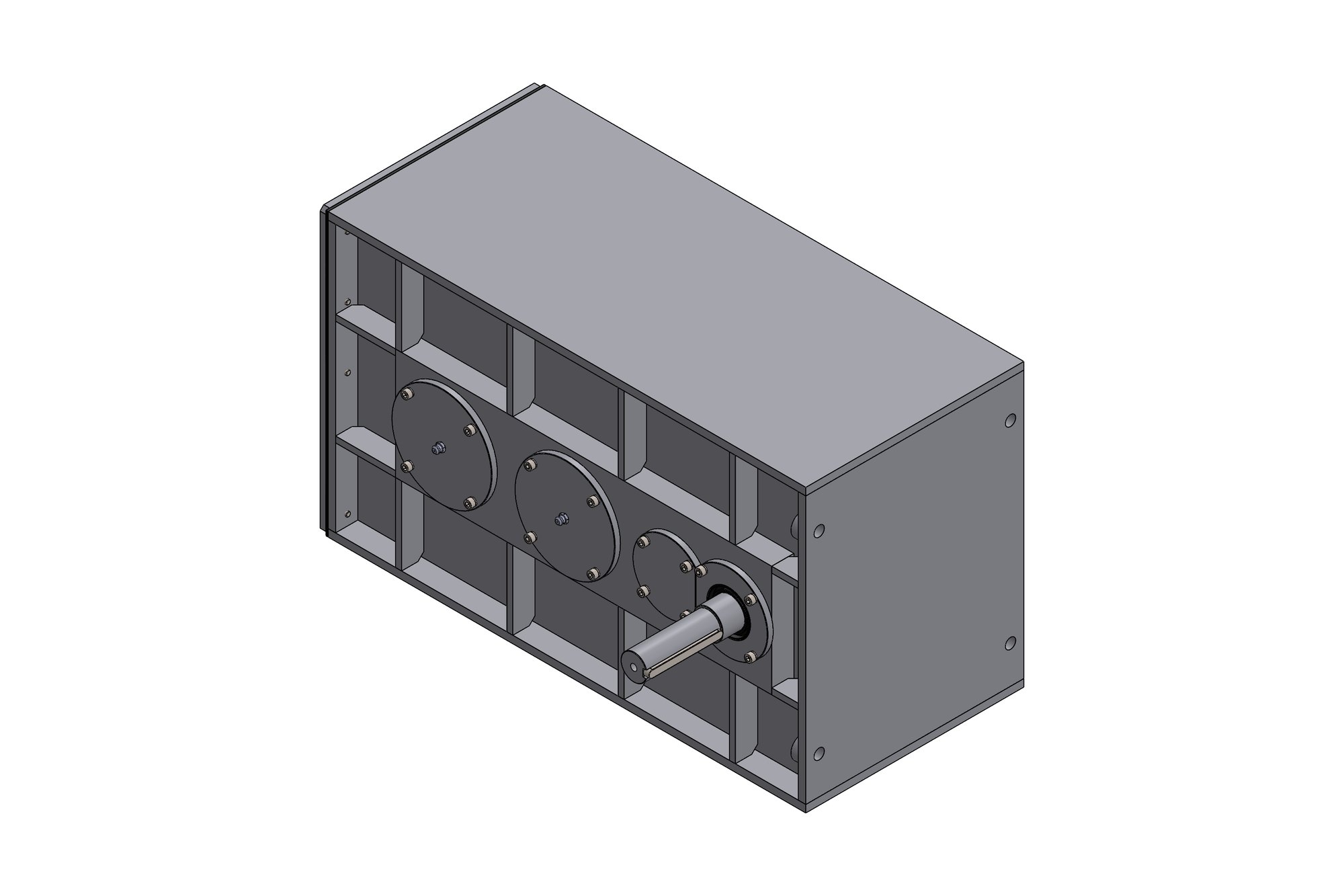
The motor mounting flange, two intermediate flanges and the cover were modelled as machined parts and then derived as casting models with 1.5° draft, 3 mm machining stock on bearing bores and faces, and cored oil passages. Separate pattern drawings were issued for each casting alongside the machining drawings, so the foundry and the machine shop each received the view they need.
What was delivered
A complete gearbox package: SolidWorks assembly with configurations for the two ratios, planetary rating reports for each stage, ring gear and sun pinion drawings with gear data and heat-treatment notes, carrier and shaft drawings, and paired casting/machining drawings with STEP pattern models for the four cast parts. The customer's foundry made patterns directly from the STEP data.
- SolidWorks assembly with ratio configurations
- Planetary rating calculation reports (both stages)
- Gear drawings with heat-treatment specification
- Casting pattern models and drawings (STEP + PDF)
- Machining drawings for the same castings
- BOM with bearings, seals and fasteners
Standards and conventions applied
- Planetary gear rating to ISO 6336 principles
- ISO 8062 casting tolerances on pattern drawings
- ISO GPS datums and runout on gear drawings
Have a similar requirement? Send the drawings, a sketch or a description — an engineer will scope it and reply with an itemised quote within one business day. Request an engineering quote.