- Client
- Electric drivetrain developer, United Kingdom (name withheld under NDA)
- Industry
- Gearboxes & Power Transmission
- Service
- FEA & CFD Simulation
- Platform
- Ansys, SolidWorks, KISSsoft
- Client region
- United Kingdom
- Analysis
- Static structural, frictional contact between tooth flanks
- Comparison
- Existing versus modified gear pair at rated torque
- Validation
- Test fixture designed for rig testing
The challenge
A gear pair had been modified — profile, face width and material — and the client wanted evidence beyond the rating calculation that the change reduced contact stress, together with a way to confirm it physically. The analysis had to isolate the mesh under load without the surrounding housing masking the result.
Our approach
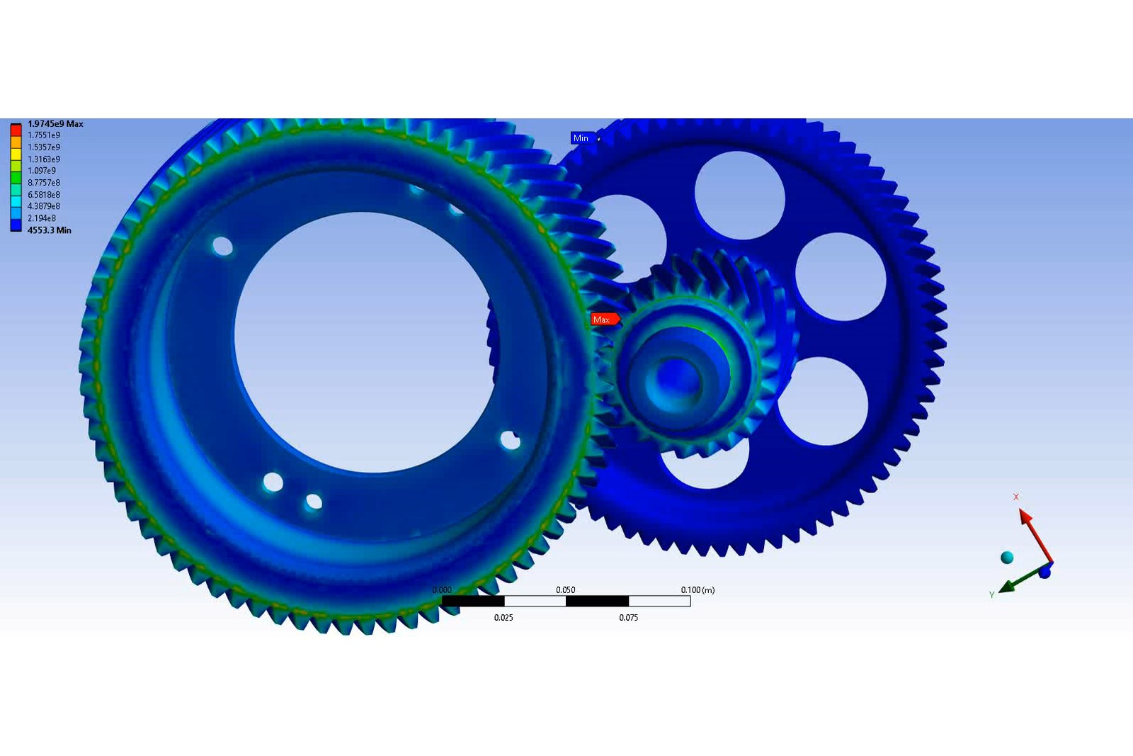
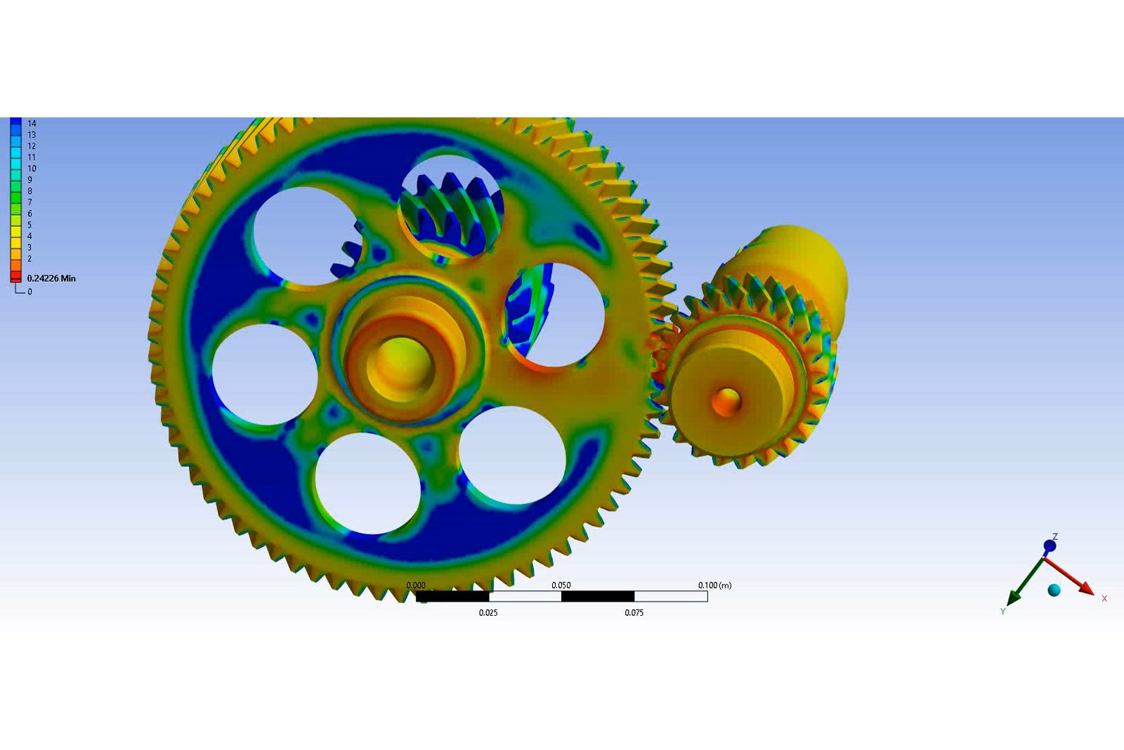
The gear train was modelled with true involute helical tooth geometry generated from the KISSsoft definition and imported into Ansys as a static structural system with frictional contact at the meshing flanks, the gears constrained on their shaft axes and rated torque applied to the input. Mesh refinement at the contact zones was increased until the peak stress converged.
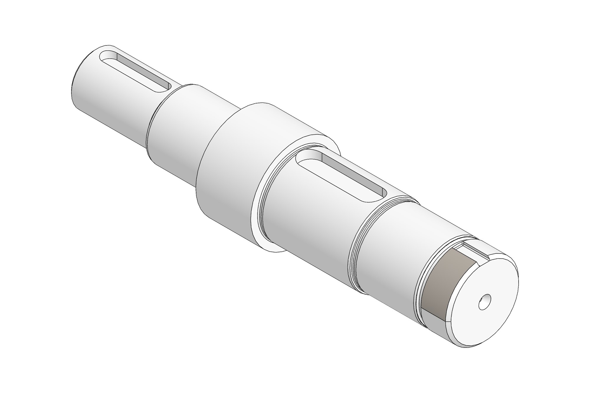
The existing and modified pairs were analysed with identical boundary conditions so the comparison was like for like, and the stress distribution along the contact line was reported alongside the peak value. A test fixture — shafts, bearing blocks and a torque-reaction arm — was designed in SolidWorks so the client could load the pair on their rig and compare measured deflection with the model.
What was delivered
The modified pair showed a lower and more evenly distributed contact stress than the original, supporting the design change, and the fixture drawings were released for manufacture so the result could be checked on the rig.
- Ansys contact analysis of both gear pairs
- Comparison report with stress plots and convergence note
- Test fixture design and drawings
- STEP exports of the analysed geometry
Standards and conventions applied
- ISO 6336 rating as the baseline for the FEA comparison
- Mesh convergence at contact zones
- Identical boundary conditions for both variants
Have a similar requirement? Send the drawings, a sketch or a description — an engineer will scope it and reply with an itemised quote within one business day. Request an engineering quote.