- Client
- Electric drivetrain developer, United Kingdom (name withheld under NDA)
- Industry
- Gearboxes & Power Transmission
- Service
- FEA & CFD Simulation
- Platform
- Ansys, SolidWorks
- Client region
- United Kingdom
- Load cases
- 7,000 N·m forward/reverse torque, 10 g shock at four orientations, bolted static
- Peak deformation
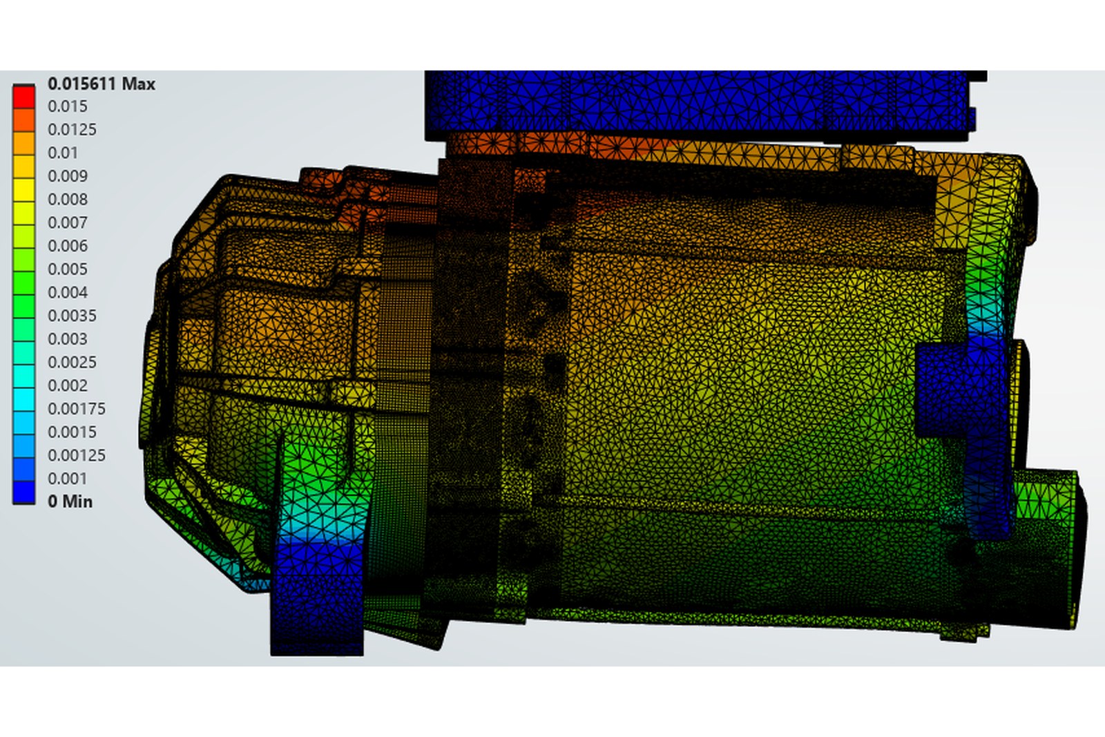
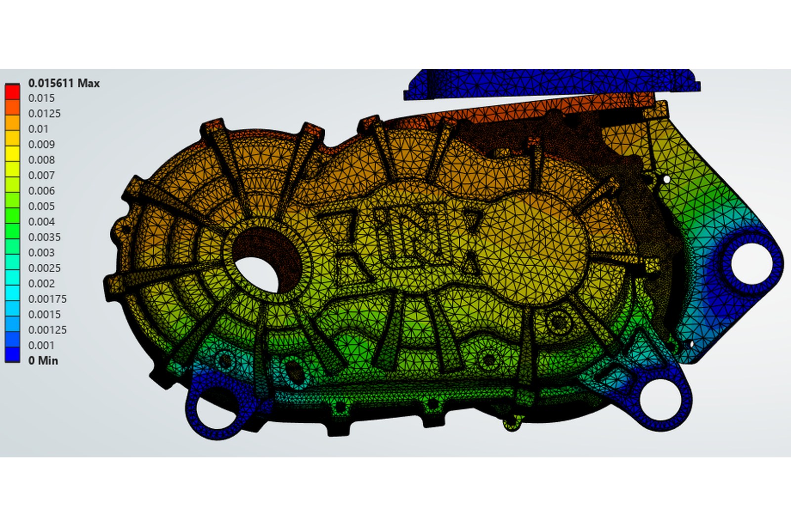
- 0.09 mm (torque case), 0.016 mm (10 g shock)
- Solver
- Ansys Mechanical, static structural
The challenge
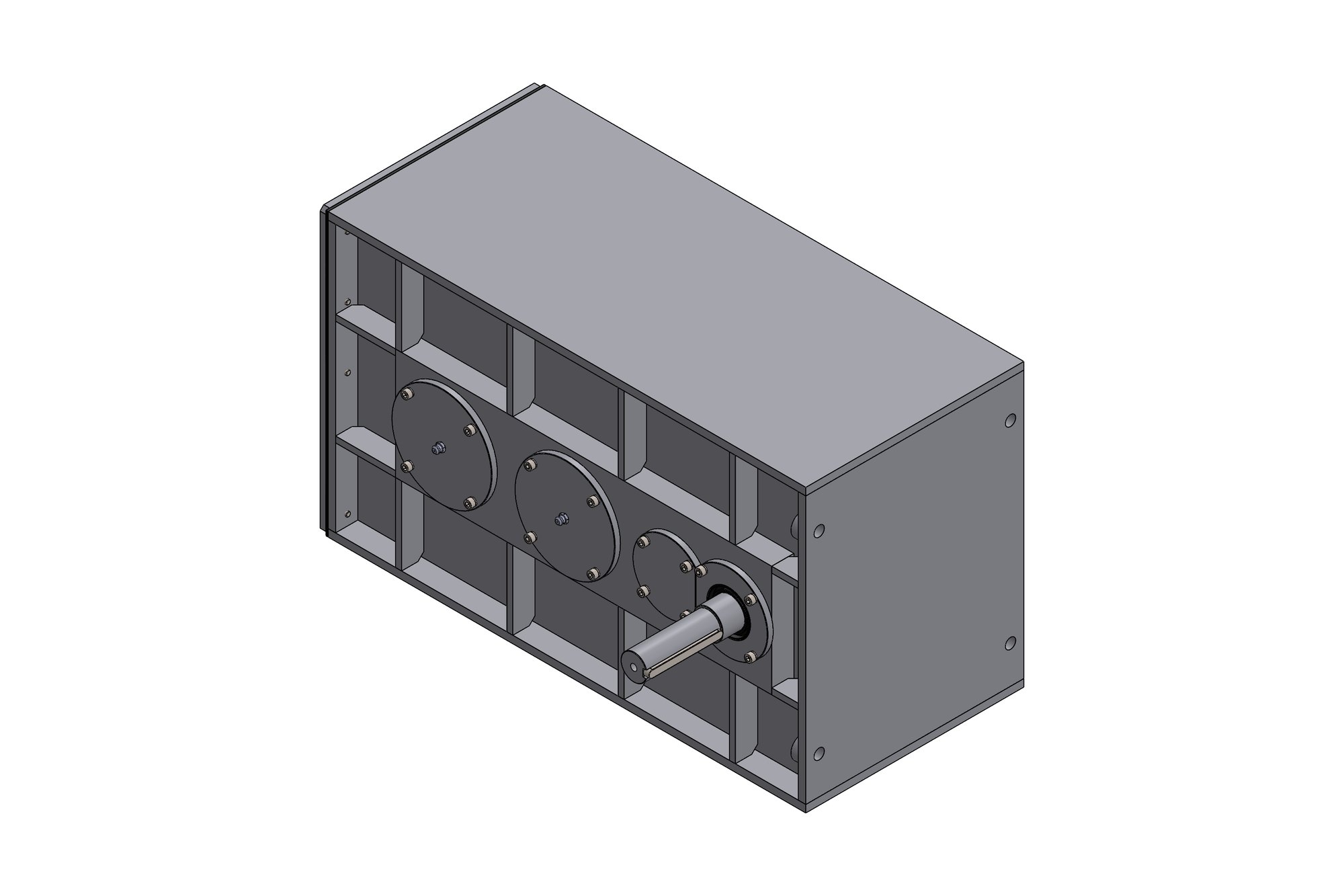
The housing carries the motor stator, the gear-train bearings and the vehicle mounting points, so torque reaction, bearing loads and road shock all pass through the same castings. The client needed to know how far the bearing bores move under peak torque — misalignment there shortens gear life — and whether the mounting ears and the motor-to-gearbox joint survive shock loading in every orientation the unit might be mounted.
Our approach
The SolidWorks housing assembly was simplified for analysis — small fillets, threads and cosmetic features removed, bolted joints represented with pretensioned bolt connections and frictional contact at the split faces — and meshed with refinement at bearing bores, ribs and mounting ears. Material data for the aluminium casting and the steel fasteners was taken from the client's specification.
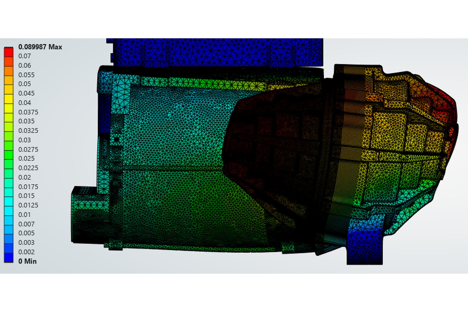
Load cases were run as separate systems in one Ansys project: 7,000 N·m forward and reverse torque applied as bearing-reaction loads, static bolted-joint cases, and 10 g shock applied at the 3, 6, 9 and 12 o'clock orientations with the unit supported at its mounting points. Total deformation, von Mises stress and bolt loads were extracted for each case and compared with the allowable values agreed with the client.
Results were presented as a short report per load case — plot, peak values, location and a note on what it means for the design — rather than a single pass/fail, so the client's engineers could decide which ribs to thicken and which to leave alone.
What was delivered
Peak deformation under forward torque was 0.09 mm, concentrated at the output end, and 0.016 mm under the worst shock orientation. The housing was revised in two places and re-run before the casting data was released; the report set has since been reused as the template for the client's later housing variants.
- Ansys Mechanical project with all load cases
- Simulation-ready simplified geometry (STEP)
- Report per load case: plots, peak values, interpretation
- Recommendations for housing revisions
Standards and conventions applied
- Static structural analysis with bolt pretension and frictional contact
- Client allowable deformation and stress limits
- Mesh convergence check at bearing bores
Have a similar requirement? Send the drawings, a sketch or a description — an engineer will scope it and reply with an itemised quote within one business day. Request an engineering quote.