- Client
- Electric drivetrain developer, United Kingdom (name withheld under NDA)
- Industry
- Gearboxes & Power Transmission
- Service
- Machine & Equipment Design
- Platform
- SolidWorks, KISSsoft, Ansys
- Client region
- United Kingdom
- Stage 1
- Input pinion 23T × 2.25 M / gear 73T × 2.25 M
- Stage 2
- Pinion 23T × 2.75 M / differential wheel
- Sealing
- Viton rotary lip seals 40×55×7 and 40×62×7
The challenge
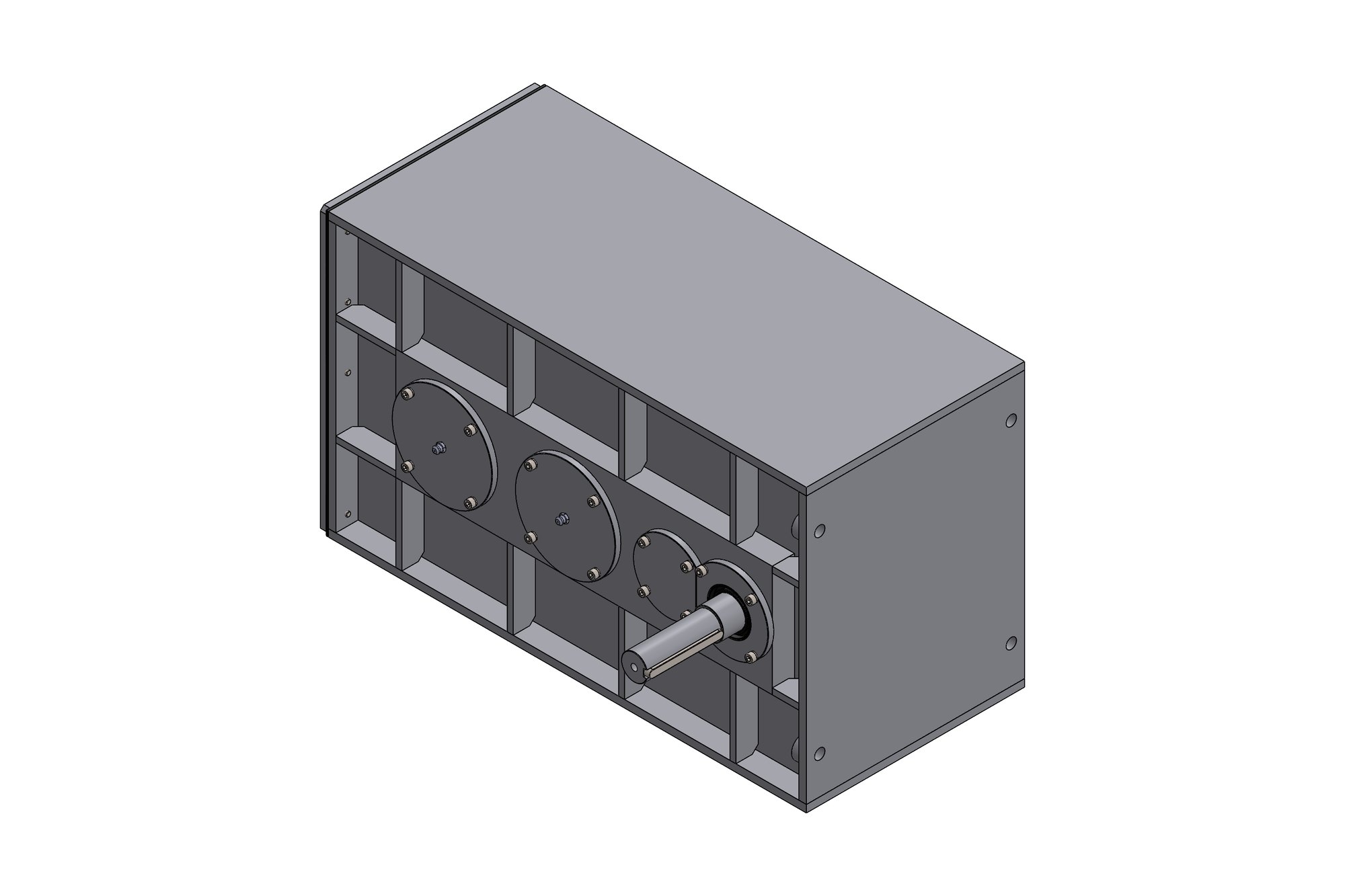
The gearbox had to deliver the vehicle's overall ratio in two helical stages while housing a torque-biasing differential of a defined size, with half shafts leaving the housing on the vehicle's track centreline. The housing had already gone through one casting revision, and the client wanted the next revision to be the last.
The unit also had to be prepared for structural simulation of the housing under combined gear and differential reaction loads, which meant a clean, simplified geometry alongside the fully detailed model.
Our approach
The gear train — 23T × 2.25 M input pinion against a 73T wheel, then a 23T × 2.75 M pinion into the differential wheel — was positioned so the differential sat on the track centreline with the half shafts clearing the housing feet. Both stages were rated for the motor's peak and continuous torque with the target bearing life.
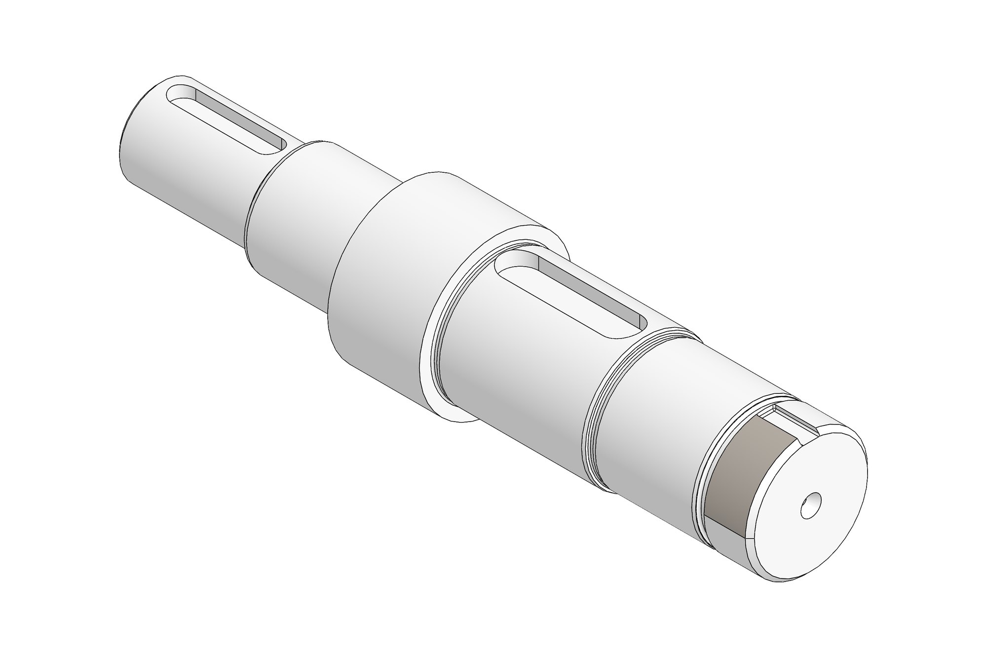
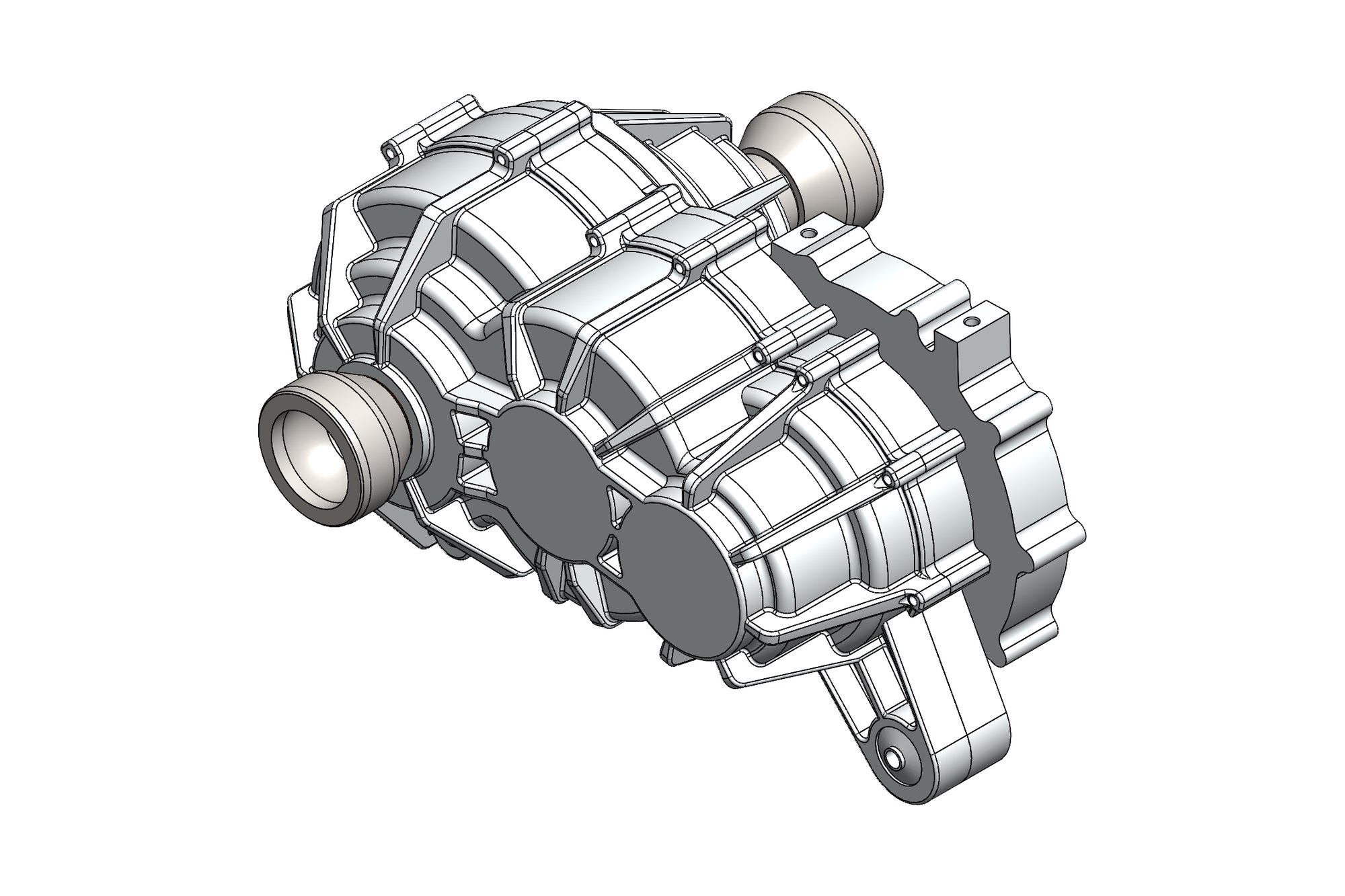
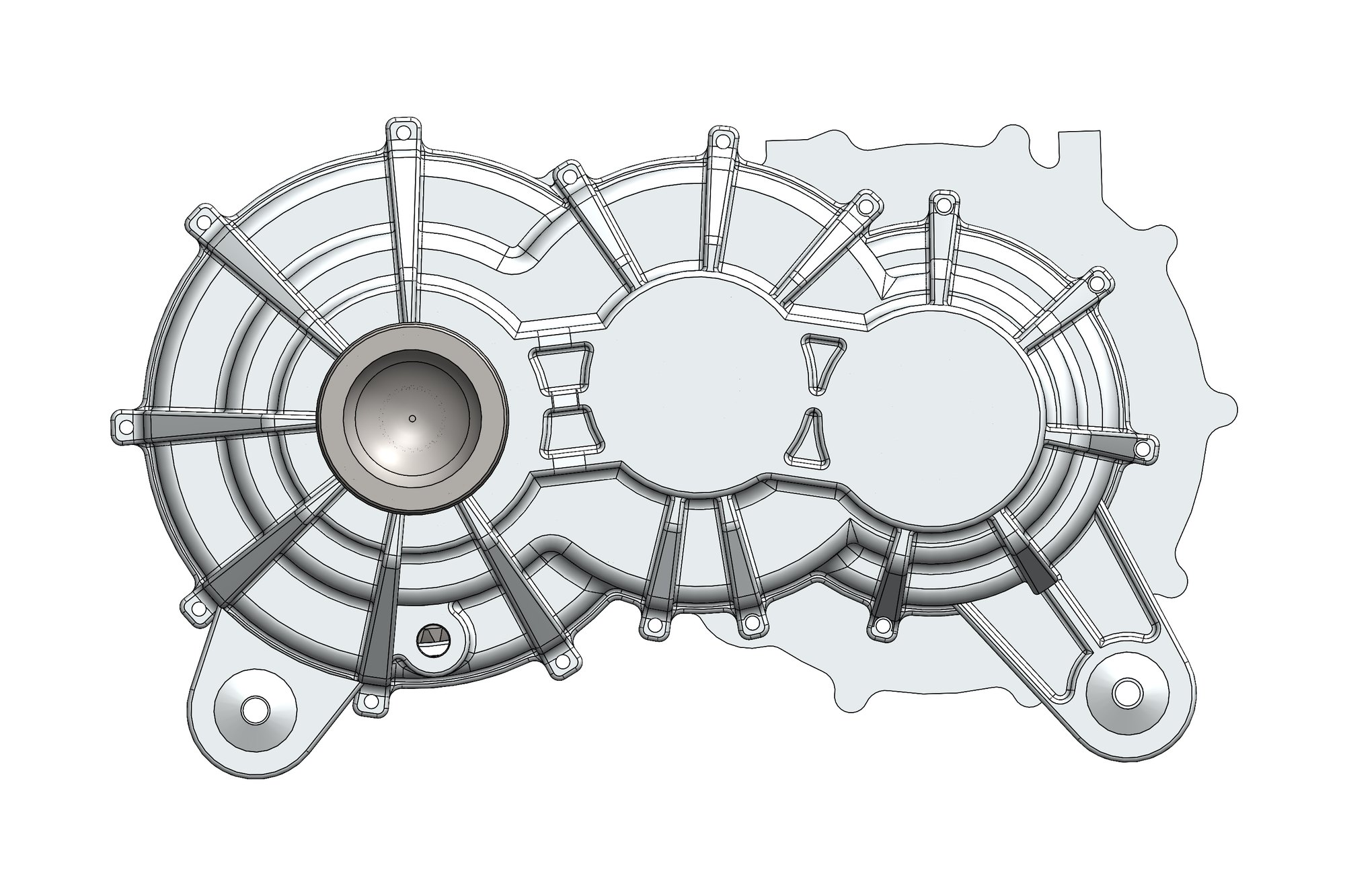
The differential body, spacer, thrust plate and trunnions were modelled as the client's supplied components, and the housing and housing spacer were revised around them: bearing seats, seal housings for the Viton lip seals, a mounting bush pattern and the fastener set (DIN 912 socket caps and DIN 6921 flange screws) were all detailed for the machinist.
A simulation-ready version of the assembly was exported as STEP with small fillets and fasteners suppressed, and the housing was checked in Ansys for stiffness at the bearing bores under peak torque reaction, confirming the revised rib pattern before the casting was committed.
What was delivered
The revised housing went to casting with a full drawing set, the assembly was delivered as native SolidWorks plus STEP, and the simulation configuration let the client's analysts run their own load cases without cleaning up the model. The two-stage layout has since been reused for a wider-track variant with longer half shafts.
- Full SolidWorks assembly with differential and half shafts
- Revised housing and spacer drawings
- Gear rating reports for both stages
- Simulation-ready STEP configuration
- Ansys housing stiffness check report
Standards and conventions applied
- ISO 6336 gear rating
- DIN 912 / DIN 6921 fastener specifications
- BS 8888 drawing practice
Have a similar requirement? Send the drawings, a sketch or a description — an engineer will scope it and reply with an itemised quote within one business day. Request an engineering quote.