- Client
- Special-purpose machine builder (name withheld under NDA)
- Industry
- Industrial Machinery & Presses
- Service
- Machine & Equipment Design
- Platform
- SolidWorks
- Client region
- India
The challenge
Mechanism design starts with what has to move, how far, and in what relationship to everything else. The linkage is the answer to that question, not the starting point. Getting this order right avoids the common trap of adapting a familiar linkage to a motion it was never suited to.
Proving the travel
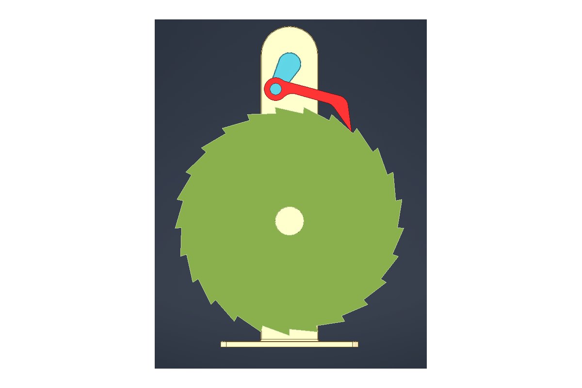
The mechanism was modelled with proper mates and driven through its full range in CAD, checking for interference at every position rather than only at the two end points. Most linkage problems appear somewhere in the middle of the travel, where a link sweeps through a space that looked clear when the mechanism was drawn at rest.
Force through the cycle
Linkage forces change through the stroke, sometimes dramatically near the ends of travel where mechanical advantage shifts. Pin diameters and link sections were sized against the worst position in the cycle, not the nominal one.


What was delivered
A motion-verified 3D assembly, manufacturing drawings for links and pins, a pivot and bearing schedule, and an assembly bill of materials.
Have a similar requirement? Send the drawings, a sketch or a description — an engineer will scope it and reply with an itemised quote within one business day. Request an engineering quote.