- Client
- Electric drivetrain developer, United Kingdom (name withheld under NDA)
- Industry
- Gearboxes & Power Transmission
- Service
- Machine & Equipment Design
- Platform
- SolidWorks, KISSsoft, Ansys
- Client region
- United Kingdom
- Layout
- Concentric input/output, motor-integrated
- Iterations
- 12+ design revisions over 18 months
- Interfaces
- Motor stator housing, inverter, CV joints
The challenge
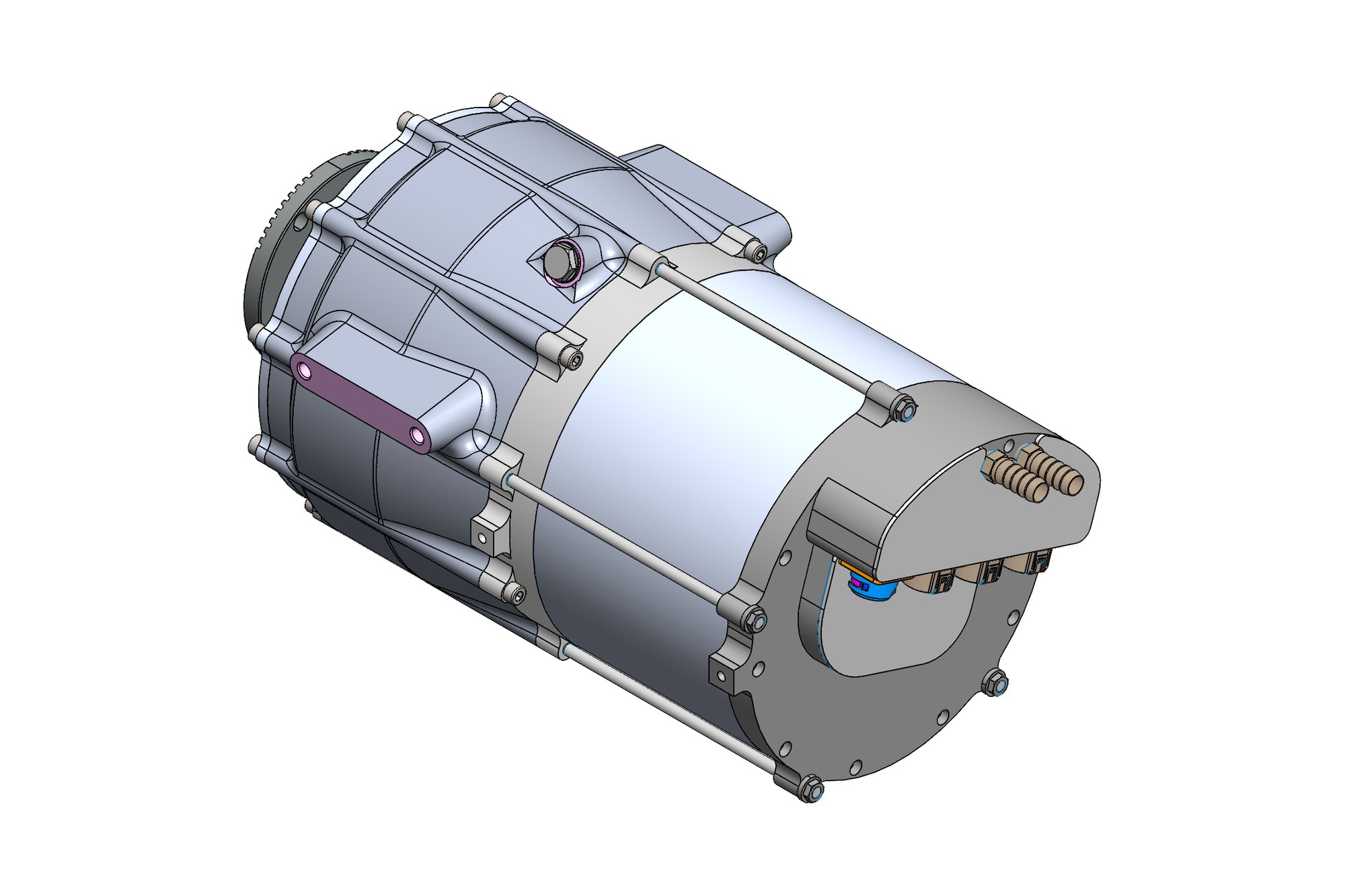
The client develops compact electric drive units for light vehicles and specialist applications. Each unit needs a reduction gearbox whose output is coaxial with the motor, that fits inside a package envelope set by the vehicle, and that can be revised quickly as motor sizes, ratios and mounting points change between customers.
Working in a different time zone, the client needed a design partner who could turn a Friday review into a revised model by Monday, keep every revision traceable, and present each change with the engineering reasoning rather than just a new file.
Our approach
The gearbox was built as a concept package assembly in SolidWorks with the motor, inverter and output joints as reference components, so every gearbox change was checked against the real envelope. Gear stages were sized in KISSsoft for the motor torque curve and target life, then checked for scuffing and bearing life at peak and continuous duty.
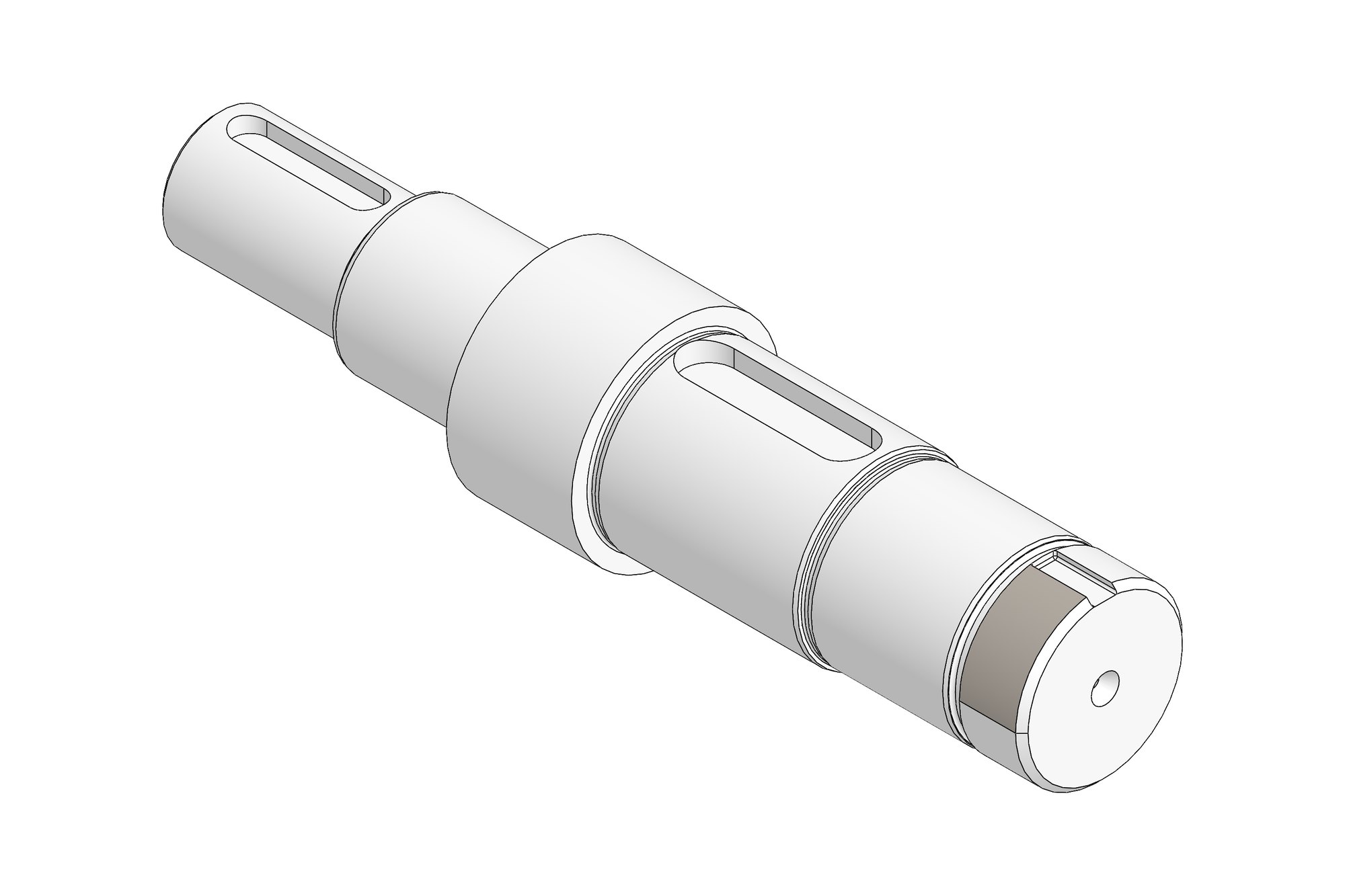
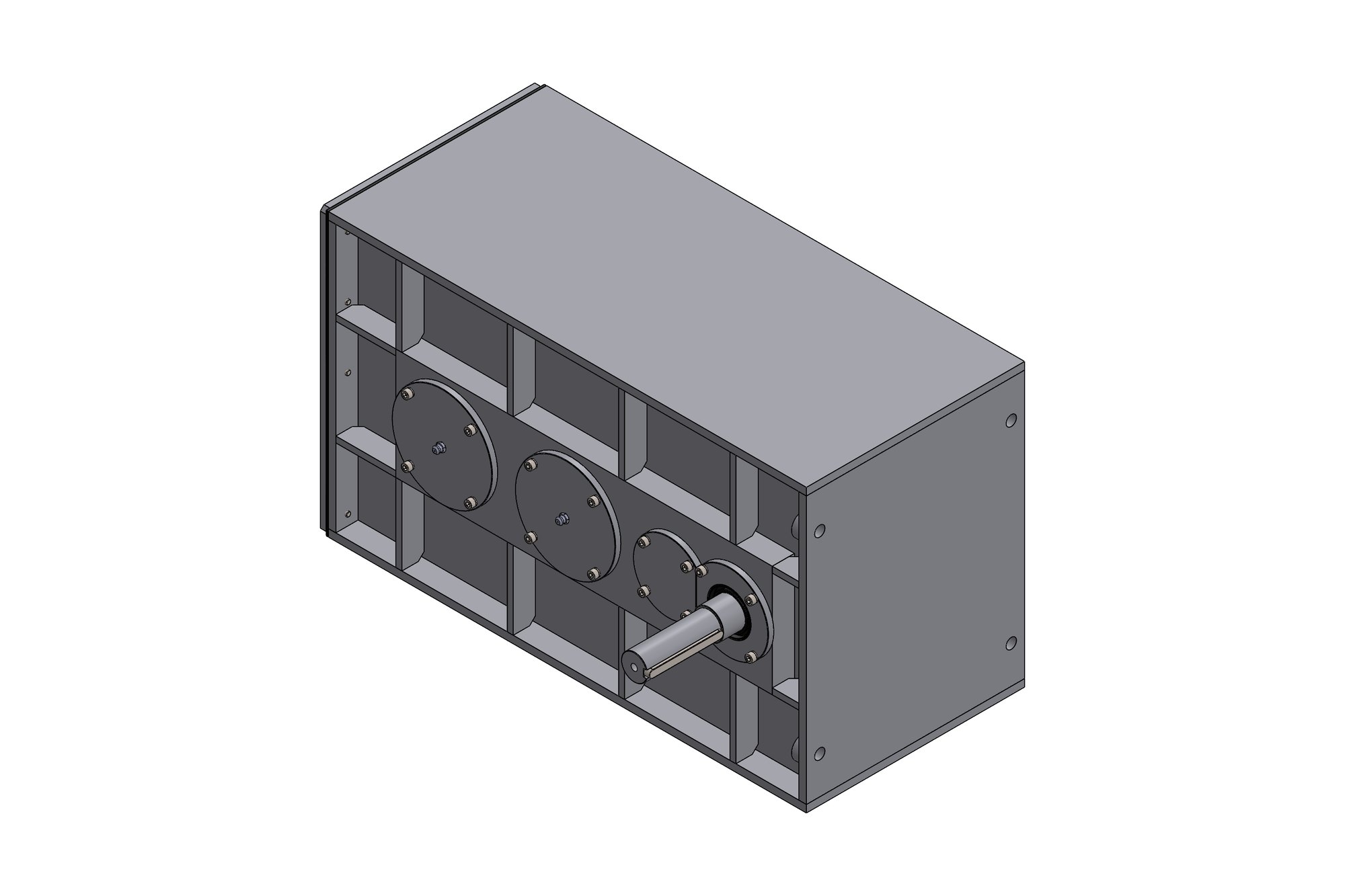
The housing was developed as a machined-from-casting part with the bearing bores, seal seats and motor spigot machined in one setting. Rotary lip seals, bearing preload, oil level and breather positions were designed for the unit's mounting orientations, including an upside-down installation variant requested mid-programme.
Revisions were run as numbered tasks — gear ratio changes, a new CV-joint interface, spacer variants, test-rig adaptors — each delivered with a short change note, updated drawings and STEP data. Critical housing sections were checked in Ansys under peak torque reaction before release.
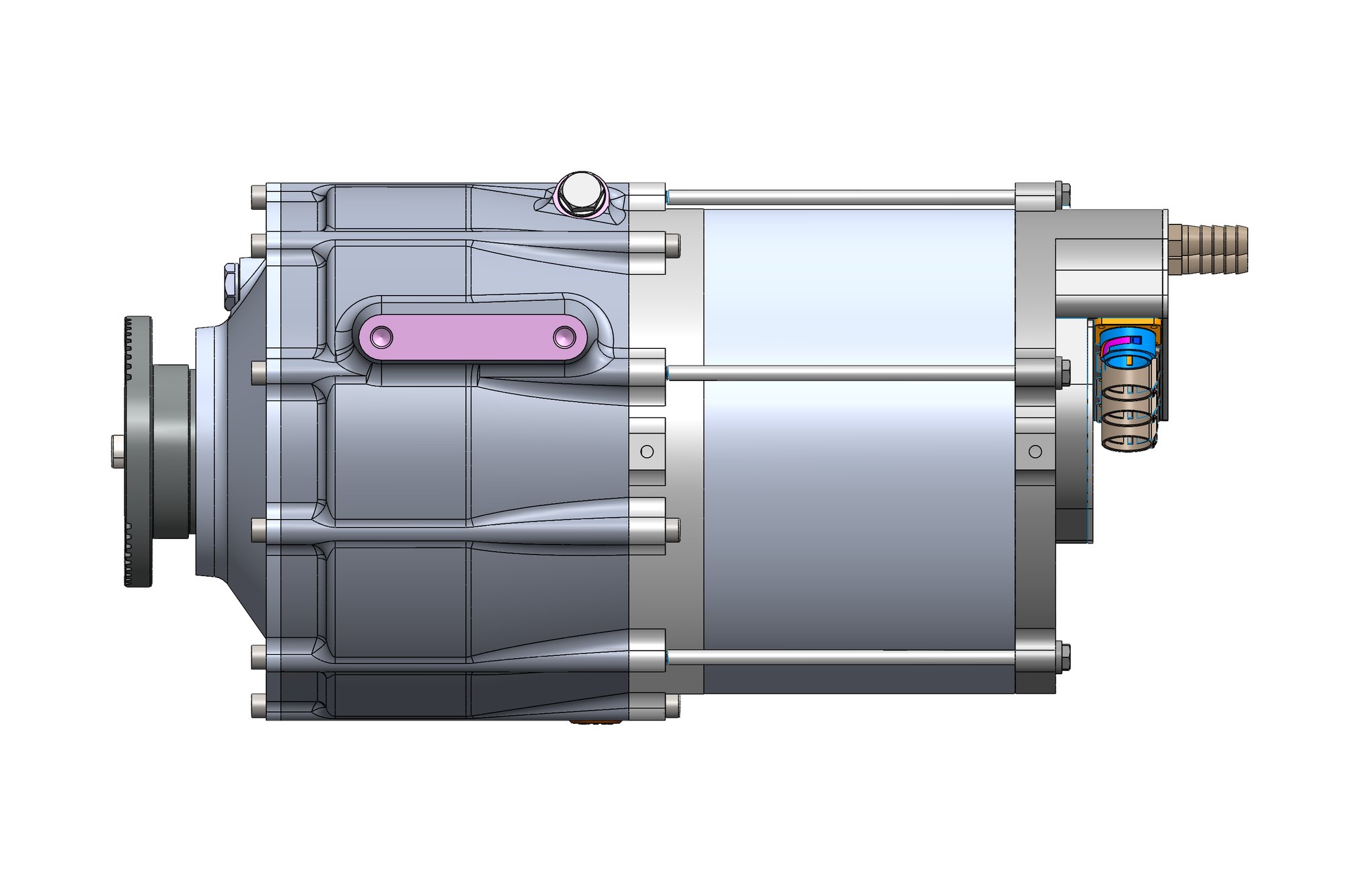
What was delivered
The client received a release-level SolidWorks design with full drawings, gear rating reports, bearing and seal specifications and test-rig adaptor designs, plus a documented revision history covering every variant. Later variants for different motor sizes were derived from the same package in days rather than weeks.
- Concept package and release assemblies in SolidWorks
- Gear rating reports and bearing life calculations
- Housing, shaft and gear drawings with GD&T
- Test-rig adaptor design
- Revision notes for each design iteration
Standards and conventions applied
- ISO 6336 gear rating via KISSsoft
- ISO GPS / BS 8888 drawing practice
- Client PDM naming and revision rules
Have a similar requirement? Send the drawings, a sketch or a description — an engineer will scope it and reply with an itemised quote within one business day. Request an engineering quote.