- Client
- Fabrication company, Australia (name withheld under NDA)
- Industry
- Sheet Metal & Steel Fabrication
- Service
- Structural Steel Detailing
- Platform
- SolidWorks
- Client region
- Australia
- Members
- 20 × 20 solid bar · 3 mm sheet strips · 20 × 12 × 3 angle
- Cut list
- 44 items · bars from 260 to 1668 mm · up to 22 off per length
- Issue
- Full assembly, arch sub-assembly, 3D PDF and STEP
The challenge
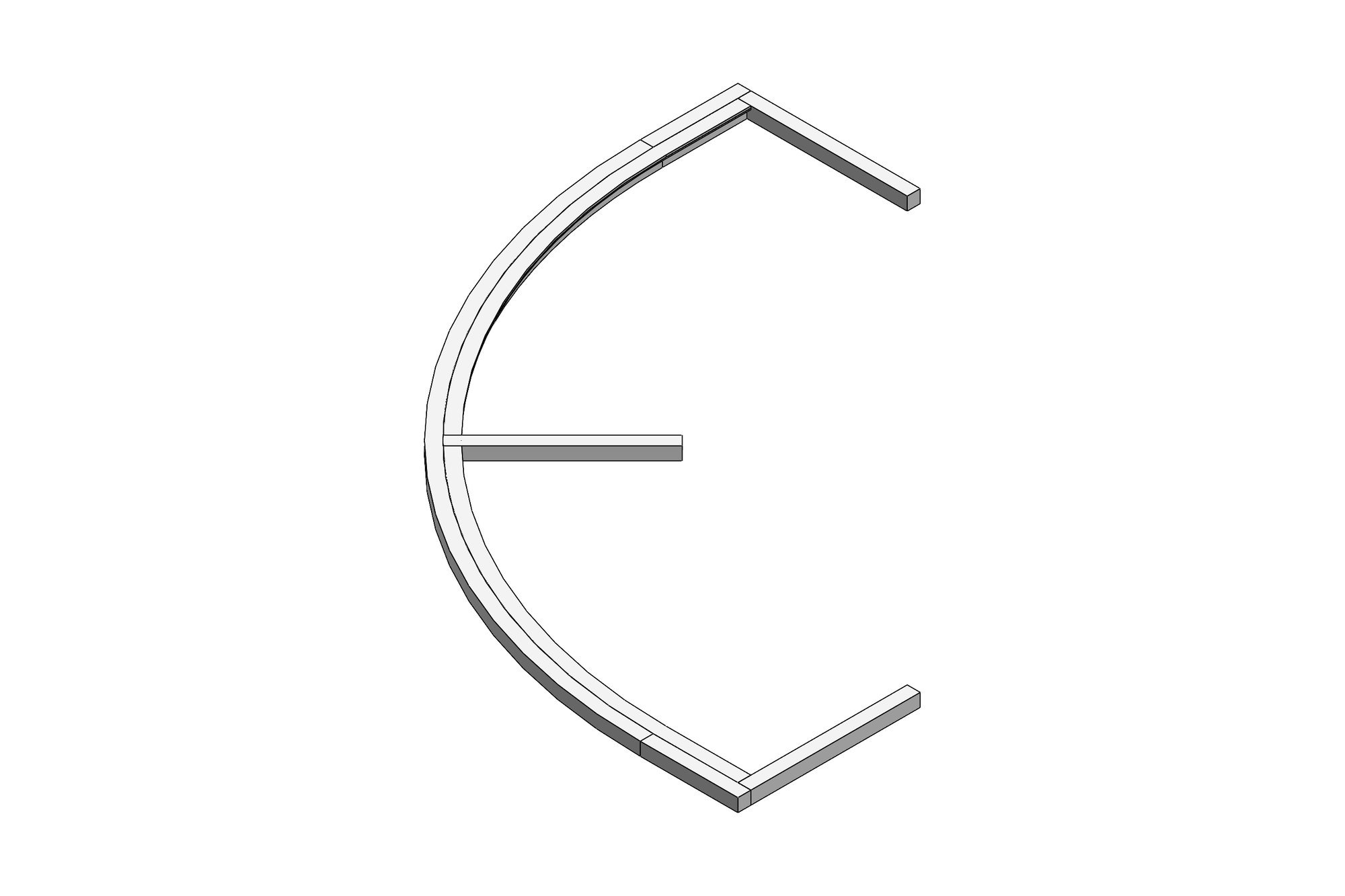
The designer supplied the look of the arch, not its construction. The fabricator needed to know how many bars, of what length, met where — and how to hold a curved lattice square while welding it — before they could price the job.
The lattice uses the same 20 × 20 bar at nine different lengths (1032, 834, 833, 832, 830, 1040, 1042, 1631, 1668 and the 260 and 340 mm infills) because the curve changes the geometry at every bay. Getting one length wrong means a visible kink in a finished, polished piece.
Our approach
The arch was modelled as a weldment-style assembly in SolidWorks with every bar as its own part, so the cut list came straight from the model: 44 line items with description, size and quantity, including 22 off 340 mm infills, 13 off 260 mm spacers and the 3 mm × 27 mm sheet strips at 813, 722 and 812 mm that form the face.
The arch sub-assembly was separated from the full assembly so the fabricator could build the curved section on a jig first, then add the straight legs and the 20 × 12 × 3 angle trims. A 3D PDF was issued with the drawing so the shop could rotate the model and see how each bar meets the next.
Three working revisions were kept as the designer adjusted the proportions; the final issue carries the full cut list on the drawing and matching STEP geometry.
What was delivered
A fabrication drawing with a 44-item cut list, the arch and full assembly models, a 3D PDF and STEP file. The fabricator priced and built the arch from the list without a site template.
- SolidWorks full and arch sub-assemblies
- Fabrication drawing with 44-item cut list
- 3D PDF for the workshop
- STEP file
- Three revision states retained
Standards and conventions applied
- Fabricator tolerance table and A3 template
- AS 1100 drawing practice
- Weldment cut-list conventions
Have a similar requirement? Send the drawings, a sketch or a description — an engineer will scope it and reply with an itemised quote within one business day. Request an engineering quote.