- Client
- Industrial gearbox builder, Gujarat (name withheld under NDA)
- Industry
- Gearboxes & Power Transmission
- Service
- Machine & Equipment Design
- Platform
- SolidWorks, KISSsoft
- Client region
- India
- Ratio layout
- 19/48 · 17/43 · 17/48 · 40/40 LH-RH
- Modules
- 2.5 · 3 · 4 mm
- Bearings
- Taper roller 33212 series
The challenge
The unit being replaced was a catalogue helical gear unit of the P2C type with a defined centre height, foot pattern and output shaft spacing. The customer wanted the same ratio and the same interface, but built locally from gears cut on their own machines, so the design had to use tooth counts and modules their hobbing shop could cut rather than the original manufacturer's proprietary set.
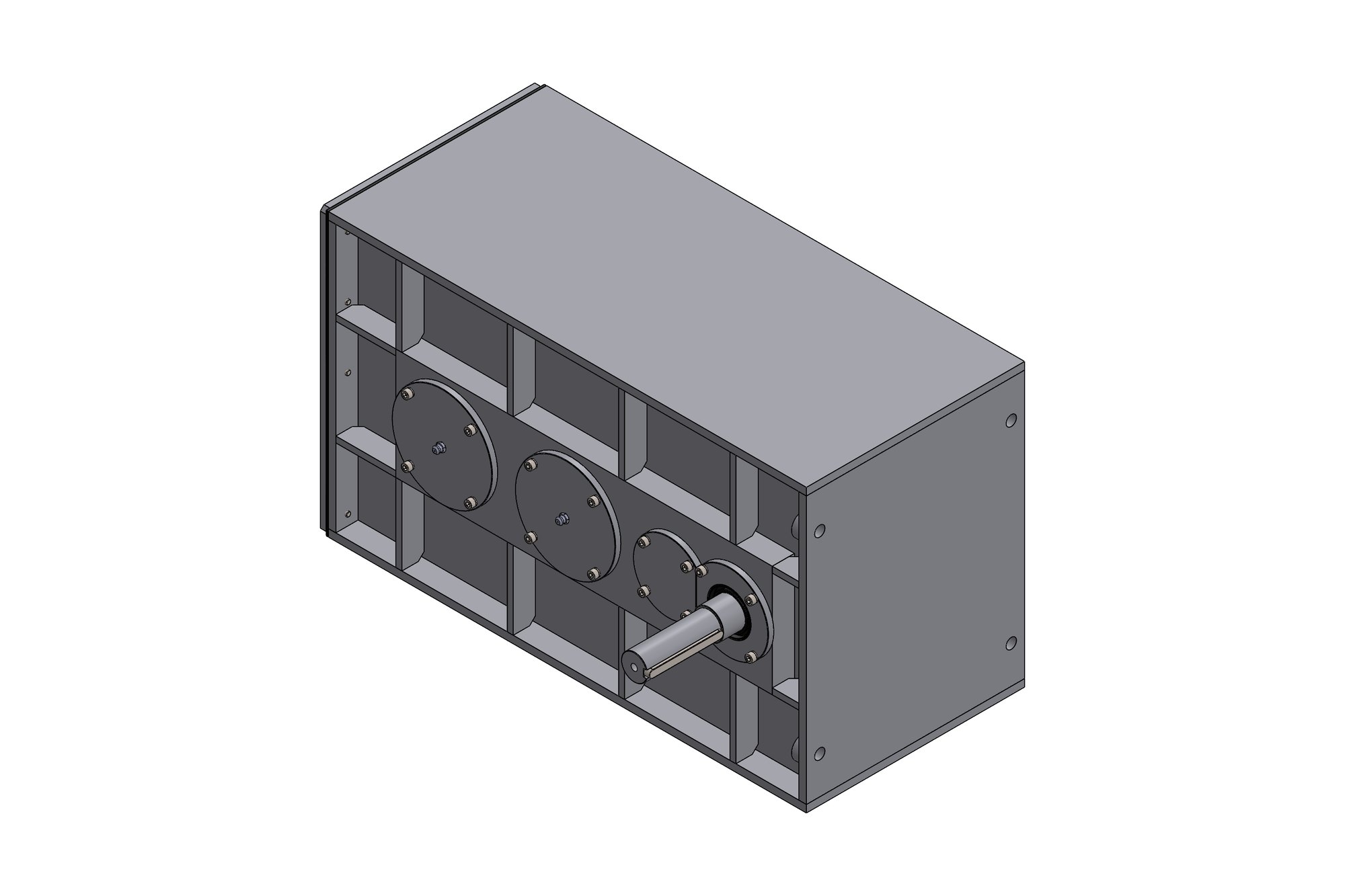
The twin output shafts rotate in opposite directions and must stay exactly on the original centres: the driven machine mounts straight onto them. Any error there would have made the gearbox useless regardless of how good the gears were.
Our approach
We started from the output end. The LH and RH 40T × 4 module output gears were fixed first at the original shaft spacing, then the third stage (17T/48T × 4M), second stage (17T/43T × 3M) and input stage (19T/48T × 2.5M) were laid out inward so that the overall ratio matched the original unit to within one percent while every centre distance stayed inside the housing envelope.
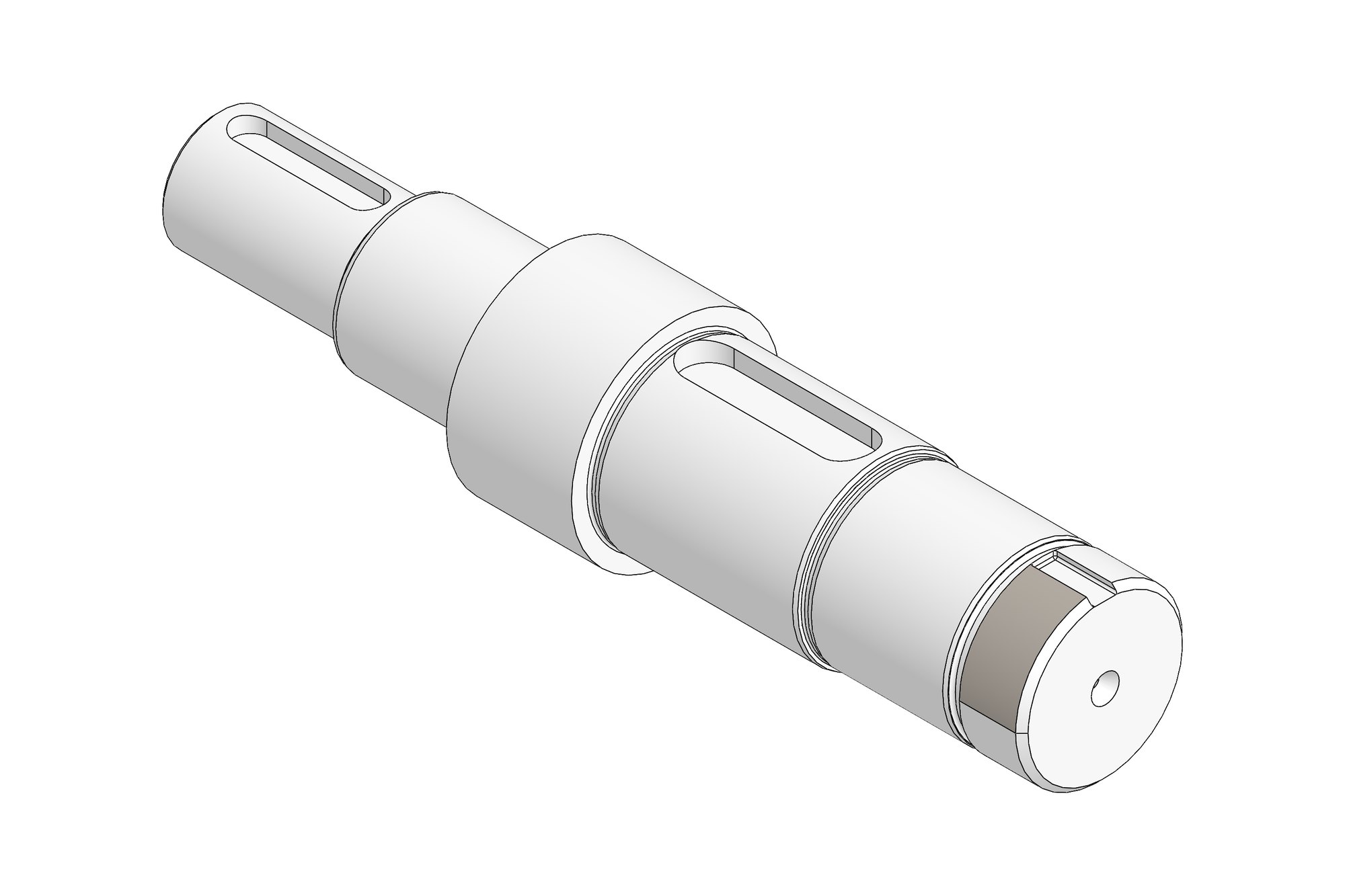
Each helical pair was rated in KISSsoft for the customer's stated power and duty, with face widths set from the rating rather than copied from the old unit. Taper-roller bearings (33212 series) were chosen to carry the combined radial and axial loads of the helical meshes, with bearing covers machined for shim-adjusted preload.
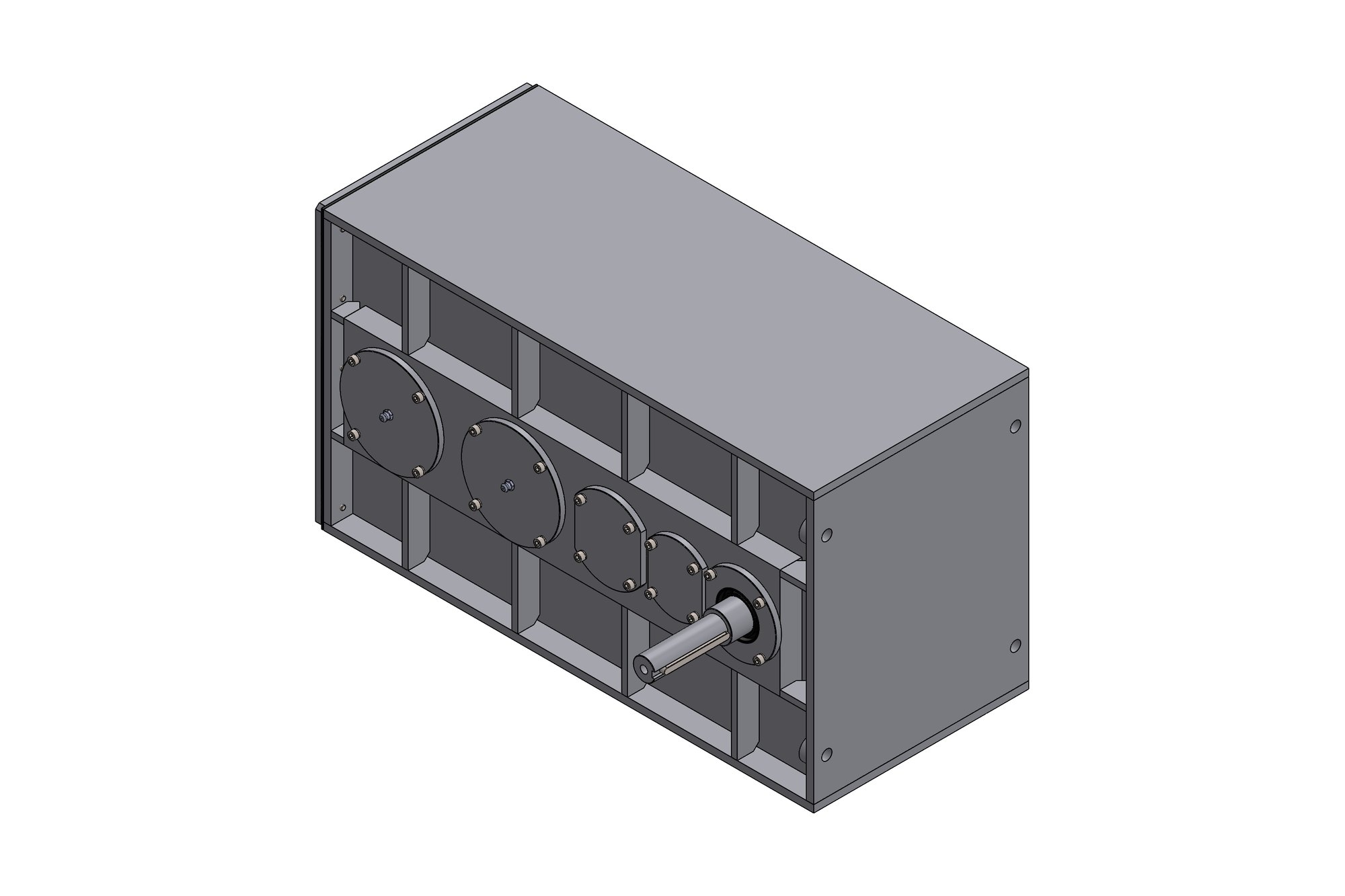
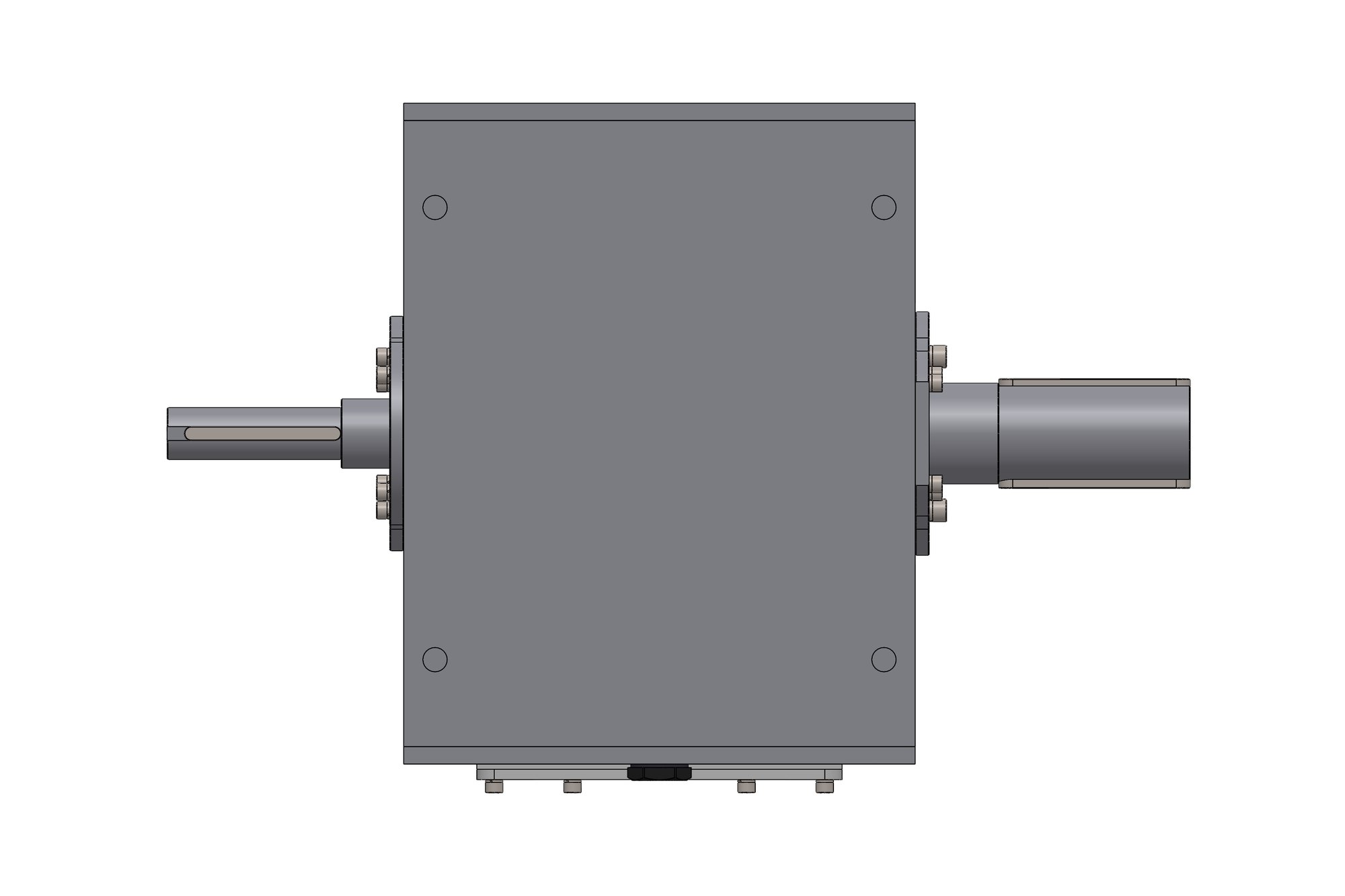
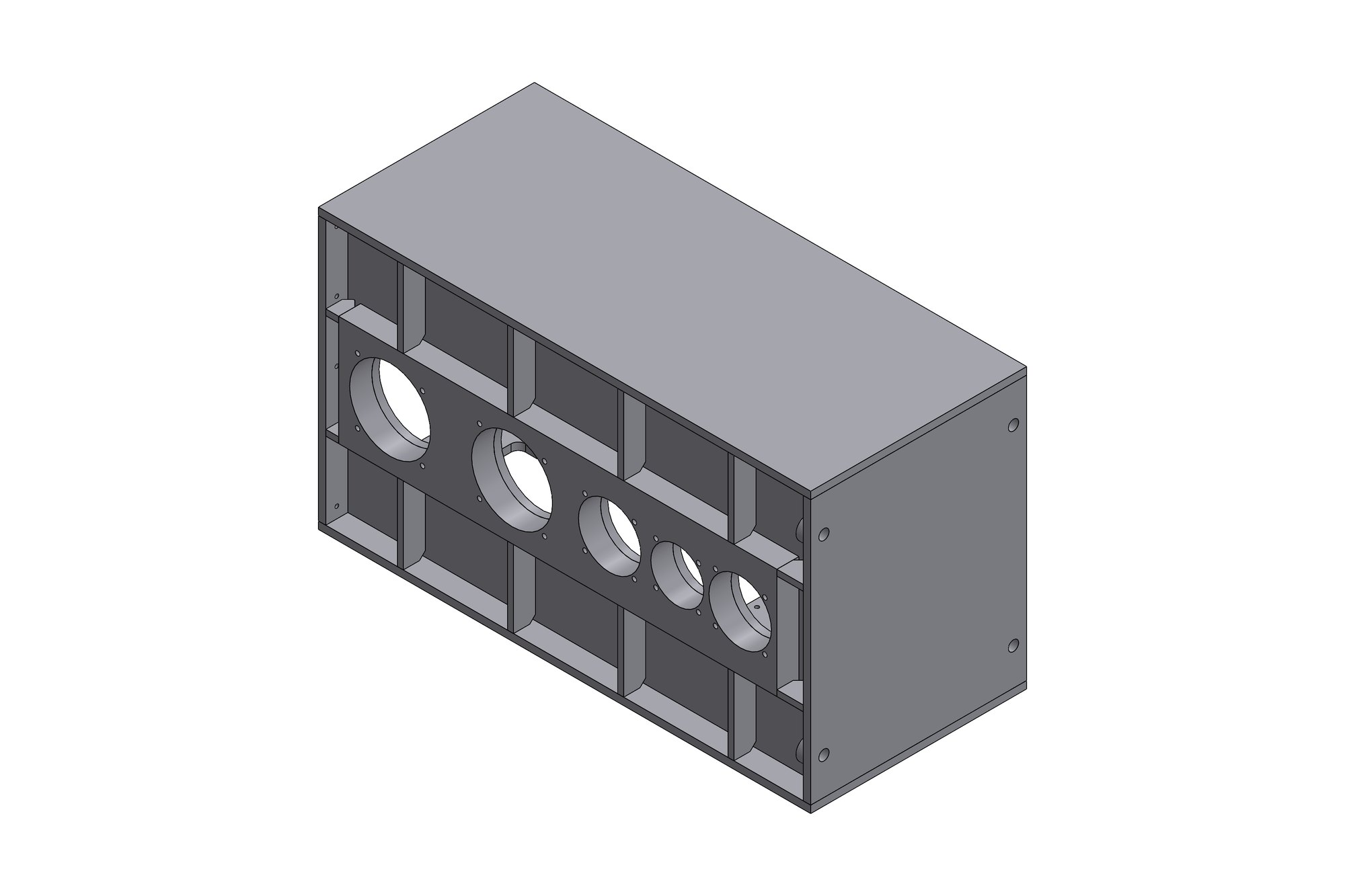
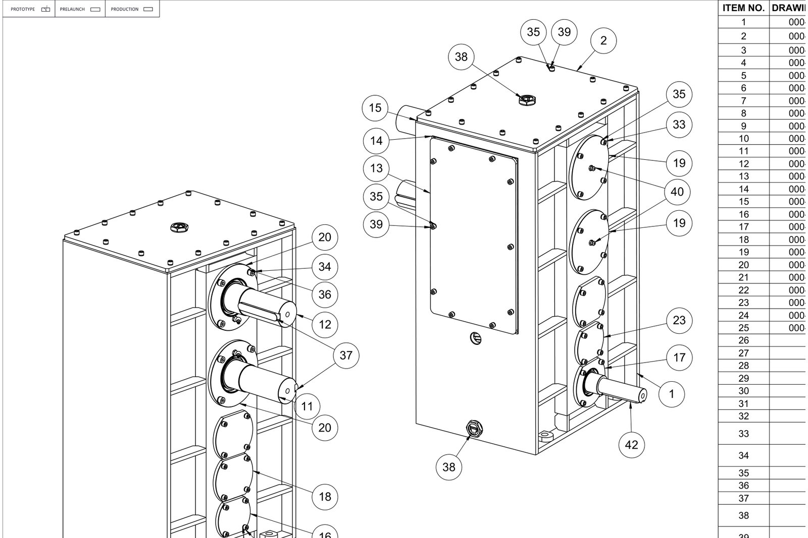
The housing is a split casting with a bolted top cover, 3 mm gaskets, closed and open end covers for each shaft and an acrylic inspection window so the mesh can be seen during commissioning. Every cover, spacer and gasket is a separate numbered part on the BOM — 40 items in total — so the shop could order castings, cut gears and fit standard parts in parallel.
What was delivered
The customer received a parametric SolidWorks assembly, an itemised general-arrangement drawing with a 40-line BOM, part drawings for the housing, covers, shafts and gears with gear-data tables, KISSsoft rating reports for every stage and STEP exports for their pattern maker. The ratio and interface match the original unit, and every gear is cuttable on their existing machines.
- Parametric SolidWorks assembly (housing, 4 gear stages, shafts, bearings, covers)
- GA drawing with 40-item BOM and sectional views
- Part drawings with gear data tables and heat-treatment notes
- KISSsoft rating reports for each helical pair
- STEP files for castings and pattern making
Standards and conventions applied
- ISO 6336 helical gear rating (KISSsoft)
- ISO GPS tolerancing with general tolerances per drawing table
- Customer title block and numbering
Have a similar requirement? Send the drawings, a sketch or a description — an engineer will scope it and reply with an itemised quote within one business day. Request an engineering quote.