
Fabricated Gearbox Housing Design
A gearbox housing designed as a welded fabrication instead of a casting — plate-by-plate detailing with weld preparation and machining allowances.
Power Transmission
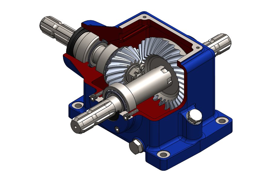
A right-angle spiral bevel gearbox modelled end to end, with the cutaway used to prove shaft, bearing and gear-mesh placement before the housing was committed to a casting pattern.
The customer needed a compact right-angle drive with defined input and output shaft positions, and wanted confidence in the internal layout before committing to a cast housing. Once a casting pattern exists, moving a bearing seat or a shaft centre is expensive, so the layout had to be right first time.
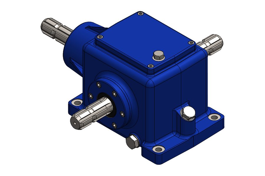
The gearbox turns drive through 90 degrees on intersecting shafts using a spiral bevel pair, whose curved oblique teeth engage progressively rather than all at once — the reason spiral bevel runs quieter and carries more load than a straight bevel of the same size. One shaft runs right through the housing and exits both sides; the mating shaft enters perpendicular to it. Both external shaft ends are splined, giving positive drive engagement without relying on a key.
Both shafts run on deep-groove ball bearings seated in dedicated housing bores, held by bearing retainers on socket head cap screws. The bevel gear is located axially by a castellated nut locked with a cotter pin — a deliberately old-fashioned choice, but one that will not vibrate loose and that a fitter can inspect at a glance. Rotary radial lip seals at each shaft exit keep oil in and contamination out.
The housing is a single cast and machined body with an open top face, drilled and tapped for a bolt-on cover so the gear set can be inspected without disturbing the shafts. Mounting feet are integrated into the casting rather than bolted on, and hex-head service plugs in the side and lower walls handle filling and draining. Section thicknesses carry the bearing loads through to the feet, since a housing that flexes lets the gear mesh wander.
The cutaway shown here is what the customer signed off on. It exposes the bearing arrangement on both shafts, the depth of the bevel mesh and how the wall thickness carries through to the mounting foot. Presenting a design this way removes most of the back-and-forth — the customer sees the mesh and the bearing spacing directly rather than inferring them from a table of dimensions.
A fully parametric SolidWorks assembly, a sectional general-arrangement drawing, individual part drawings for housing and shafts, and a bill of materials covering the bought-out bearings and seals. Because the model is parametric, a change in ratio or centre distance propagates through the drawings instead of requiring a redraw.
Send us the part or the drawing and we'll tell you honestly whether it's a fit — under NDA if you'd prefer.
Project Gallery
More Work
A gearbox housing designed as a welded fabrication instead of a casting — plate-by-plate detailing with weld preparation and machining allowances.
Primary reduction gearbox for agricultural machinery — designed for shock loading, field conditions and serviceability with basic workshop tools.
Secondary reduction gearbox matched to an existing agricultural primary drive — designed to bolt onto the established mounting interface.
Send us the part, the drawing, or just a description of the problem. We'll come back with a scope, a timeline and an itemised quote — usually within one business day, and under NDA if you prefer.