
Textile Machine Reverse Engineering
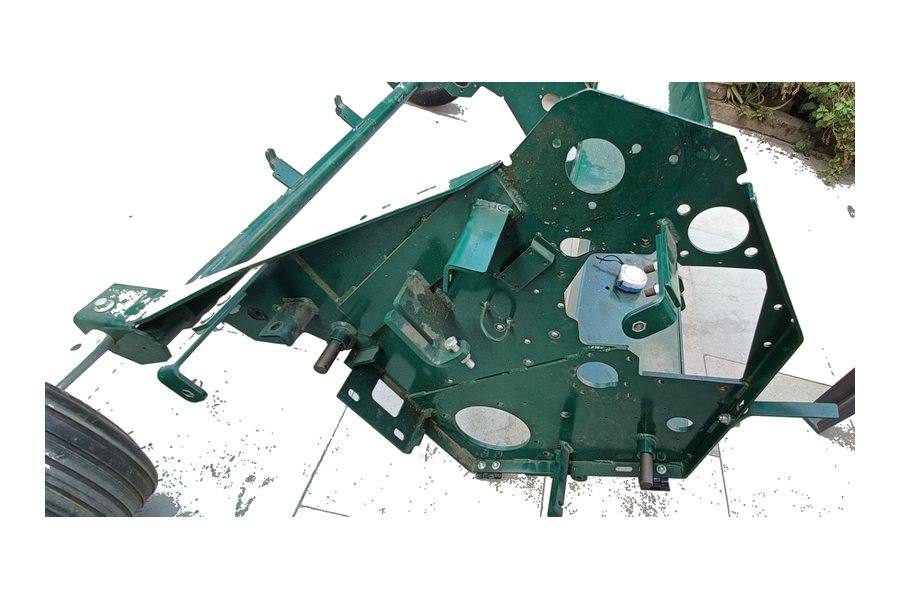
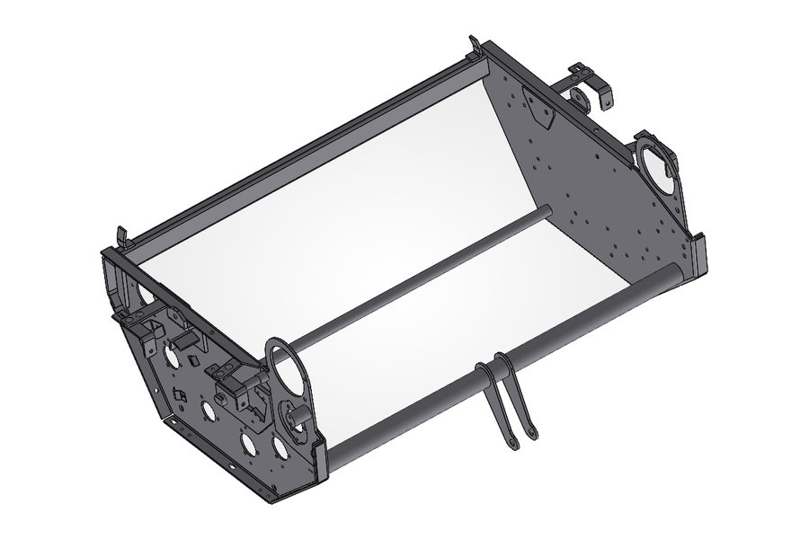
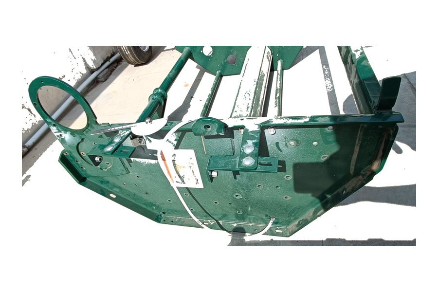
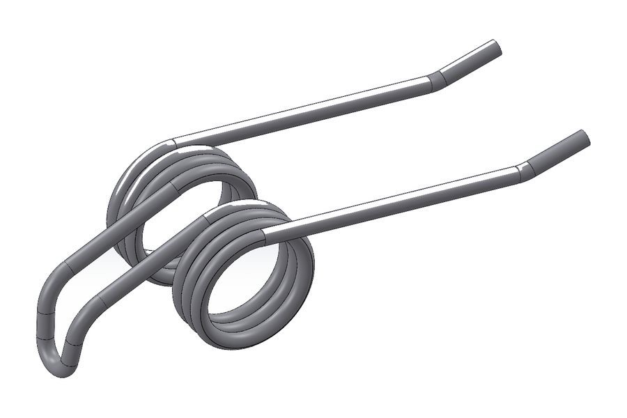
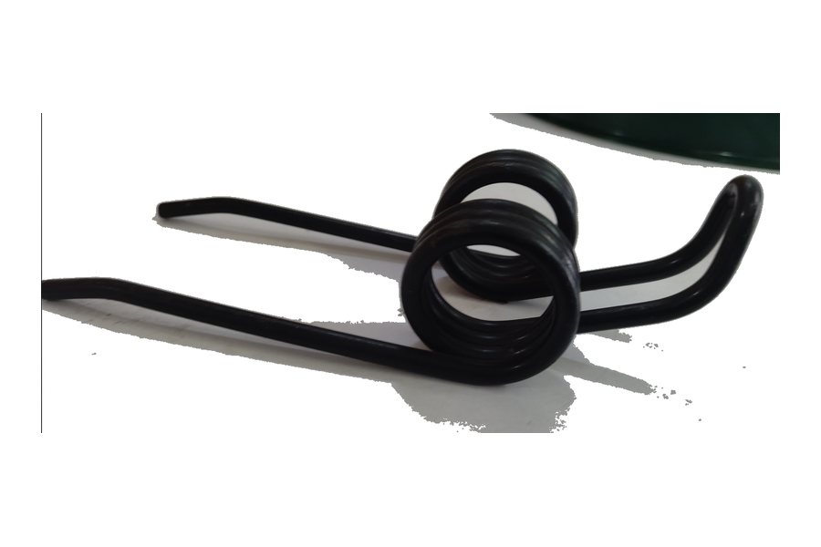
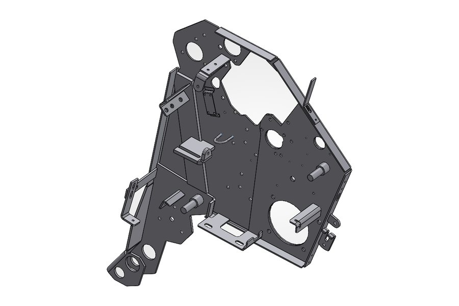
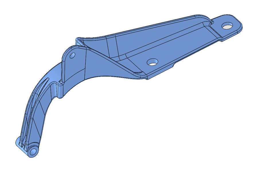
Reverse engineering a textile machine with no surviving drawings — measured, modelled as a full assembly and re-documented for spare part manufacture.
Reverse Engineering
Taking 3D scan data all the way to a clean parametric model — not a mesh that merely looks like the part, but a solid you can edit and manufacture from.
This is the most common misunderstanding about 3D scanning. A scan produces a mesh — millions of triangles describing a surface. It captures shape, but it has no features, no dimensions and no design intent. You cannot change a diameter on a mesh, because the mesh does not know it has one.
Raw scan data arrives with noise, gaps where the scanner could not see, and stray geometry from the fixturing. Before any modelling begins the mesh is cleaned up, holes are filled and the part is aligned to a sensible coordinate system — usually its functional datums rather than wherever it happened to sit on the scanner.
The real work is interpretation: recognising that a scanned region is a cylindrical boss, reading its true axis and diameter from the data, and rebuilding it as a modelled feature. Done properly, the result is a parametric solid whose dimensions are round numbers where the original design intended round numbers — not 49.97 mm because that is what a worn part measured.
The finished model is compared back against the original scan as a deviation check. That comparison is what separates a model that is genuinely accurate from one that merely looks convincing, and it is the point at which the work can be signed off with confidence.
Cleaned scan data, a fully parametric CAD model rebuilt with proper features, a deviation report against the original scan, and manufacturing drawings.
Send us the part or the drawing and we'll tell you honestly whether it's a fit — under NDA if you'd prefer.
Project Gallery
More Work
Reverse engineering a textile machine with no surviving drawings — measured, modelled as a full assembly and re-documented for spare part manufacture.
3D CAD design of a right-angle spiral bevel gearbox — splined shafts, deep-groove ball bearings and a cast housing, proven in a full sectional view.
A gearbox housing designed as a welded fabrication instead of a casting — plate-by-plate detailing with weld preparation and machining allowances.
Send us the part, the drawing, or just a description of the problem. We'll come back with a scope, a timeline and an itemised quote — usually within one business day, and under NDA if you prefer.