- Client
- Textile finishing machinery OEM, Gujarat (name withheld under NDA)
- Industry
- Textile & Process Machinery
- Service
- Machine & Equipment Design
- Platform
- Solid Edge, AutoCAD
- Client region
- India
- Configurations
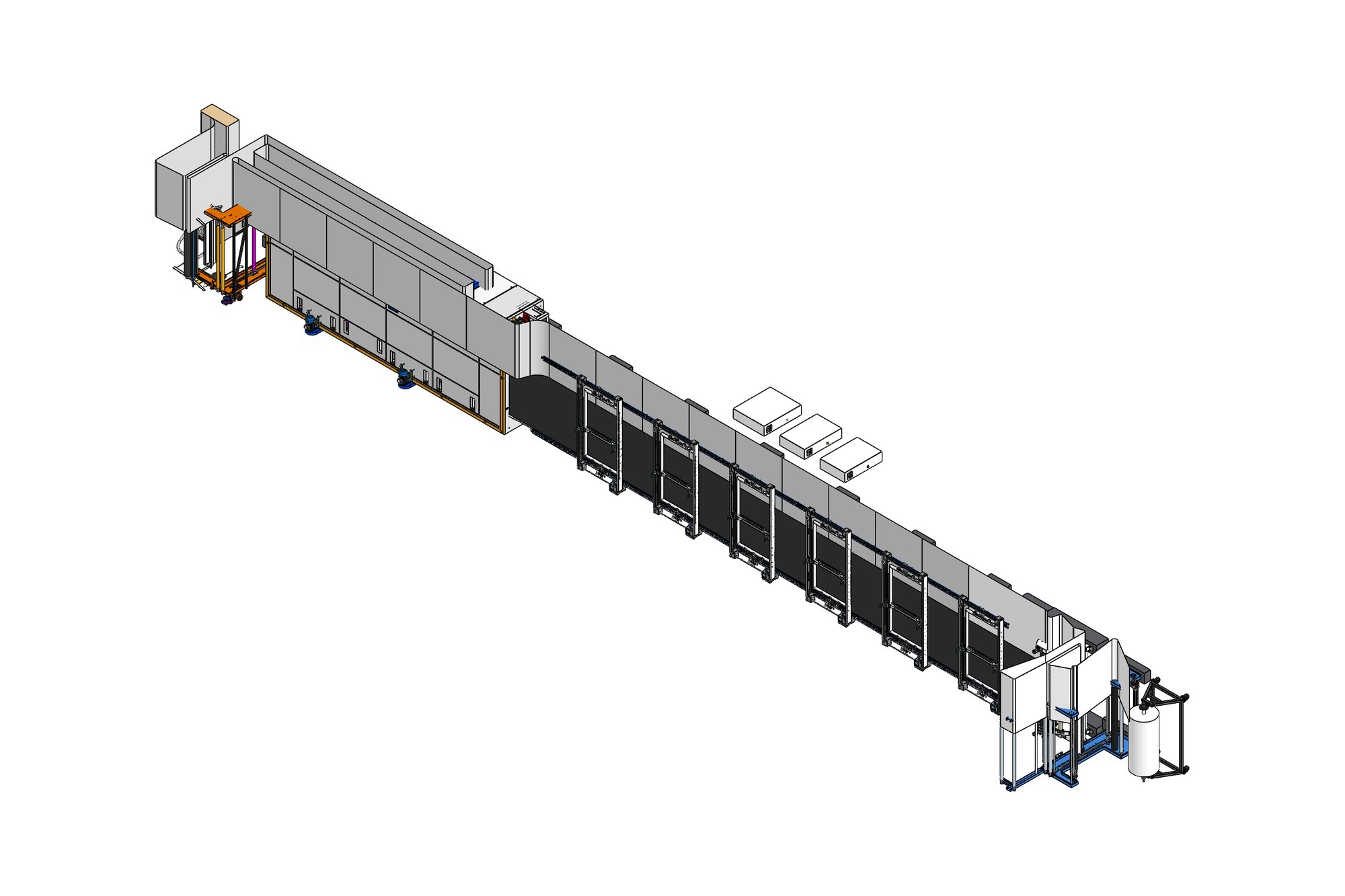
- 5-chamber and 8-chamber lines
- Sections
- Entry, mangle, overfeed, chambers, exit
- Platform
- Solid Edge assemblies, DFT drawings, STEP
The challenge
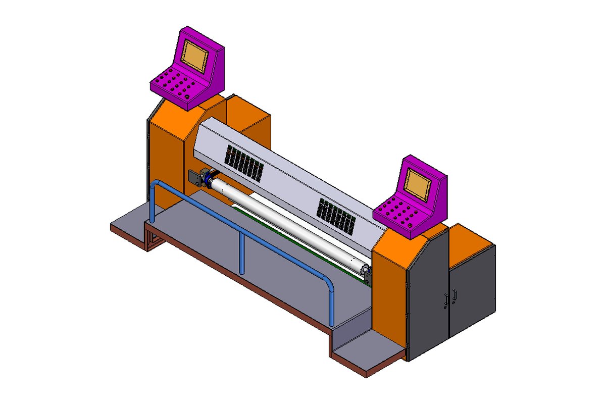
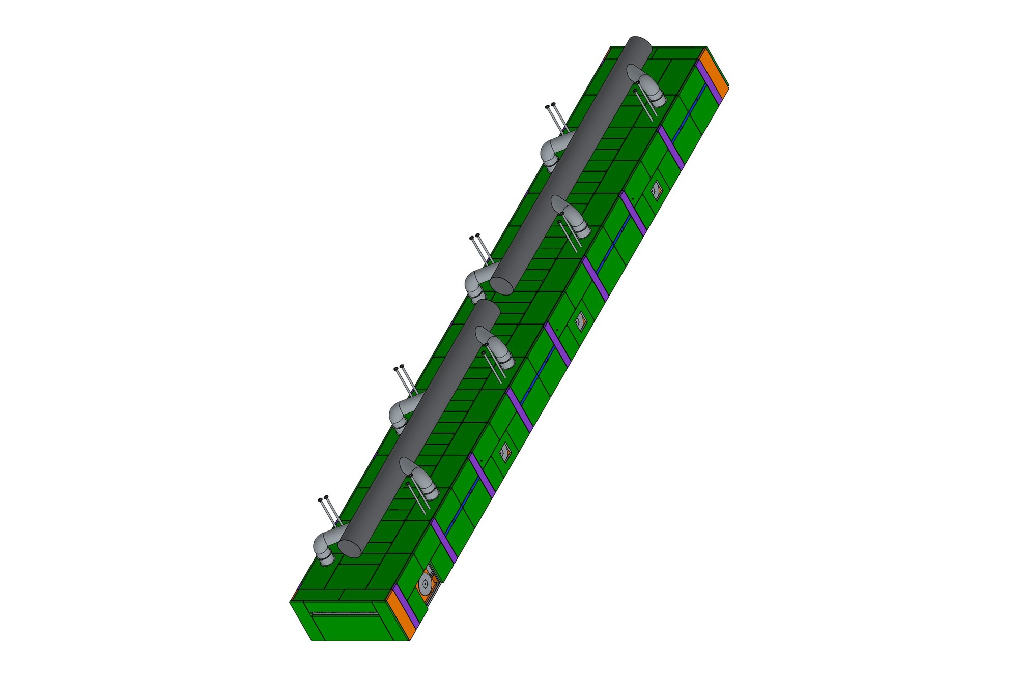
Stenter chambers are modular — a customer orders five, six or eight — so the chamber had to be designed once as a repeatable module with the duct work, nozzle plates, chain rails and insulated panels all referenced from the same frame. The mangle needed a trough lifting and lowering unit and pressure-roll assembly that fitted the entry frame on every configuration.
The OEM works in Solid Edge and issues DFT drawings with a fabrication tolerance table for unspecified dimensions. All deliverables had to be native and follow that table.
Our approach
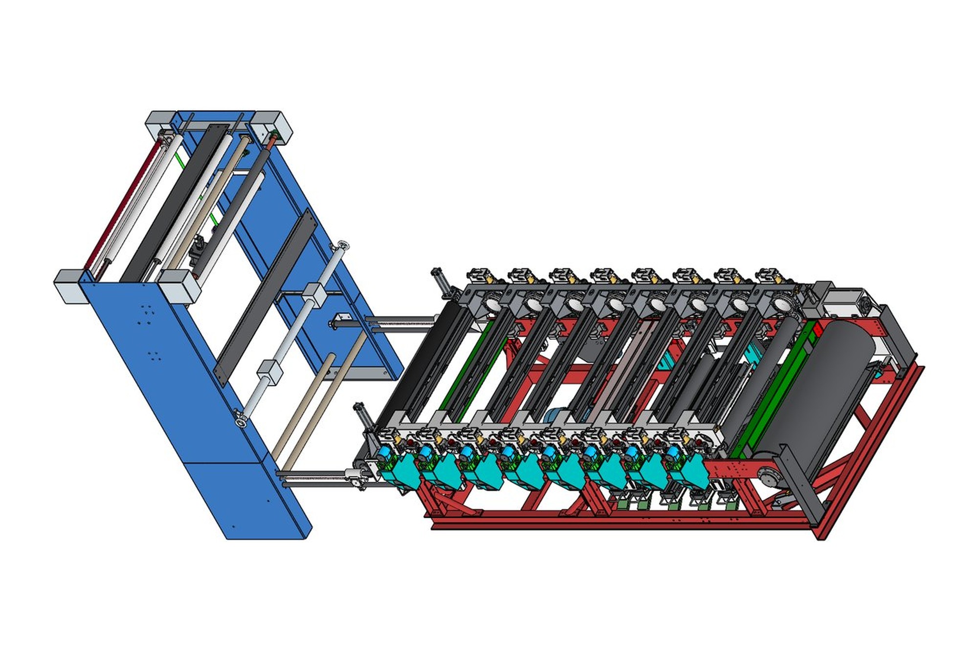
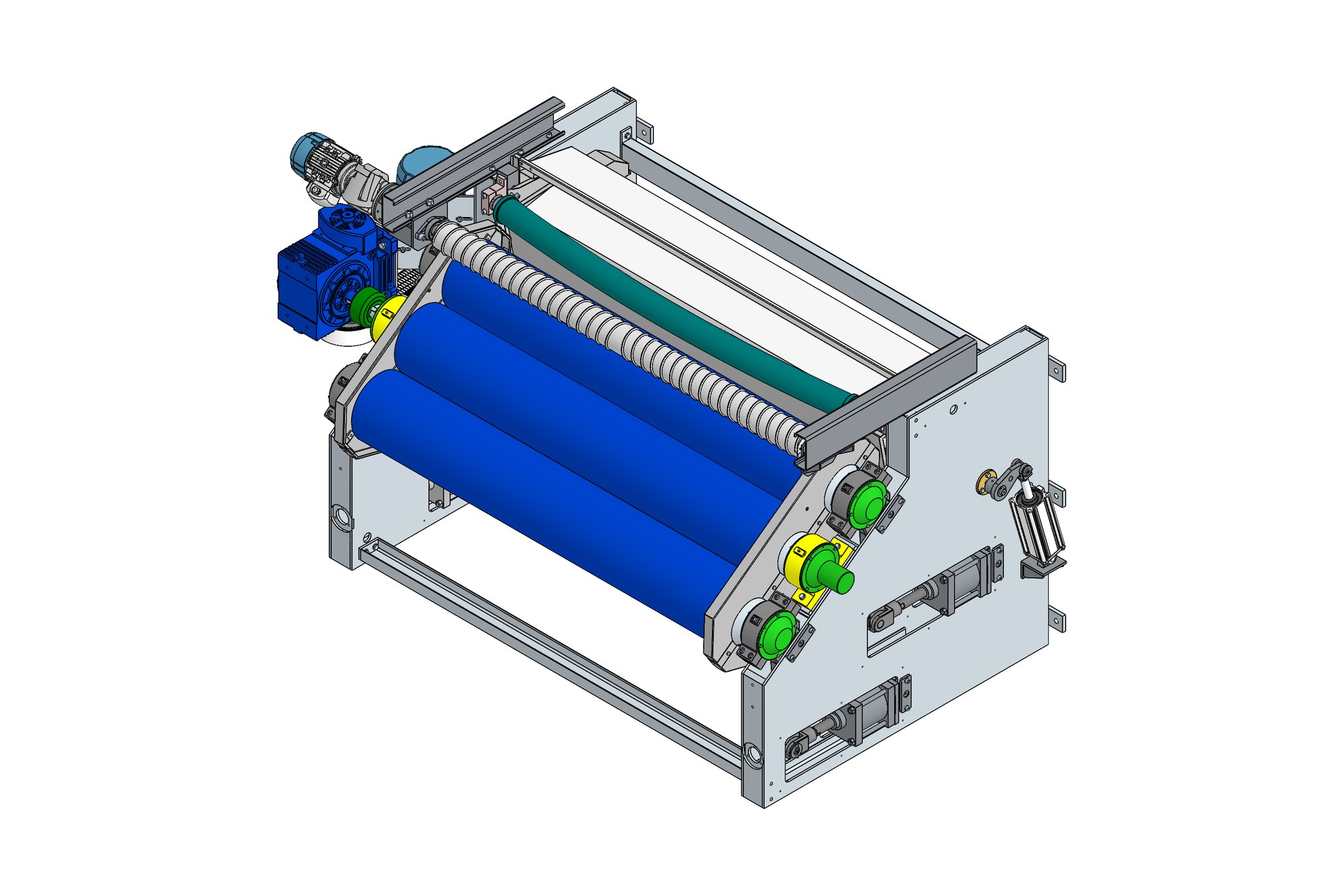
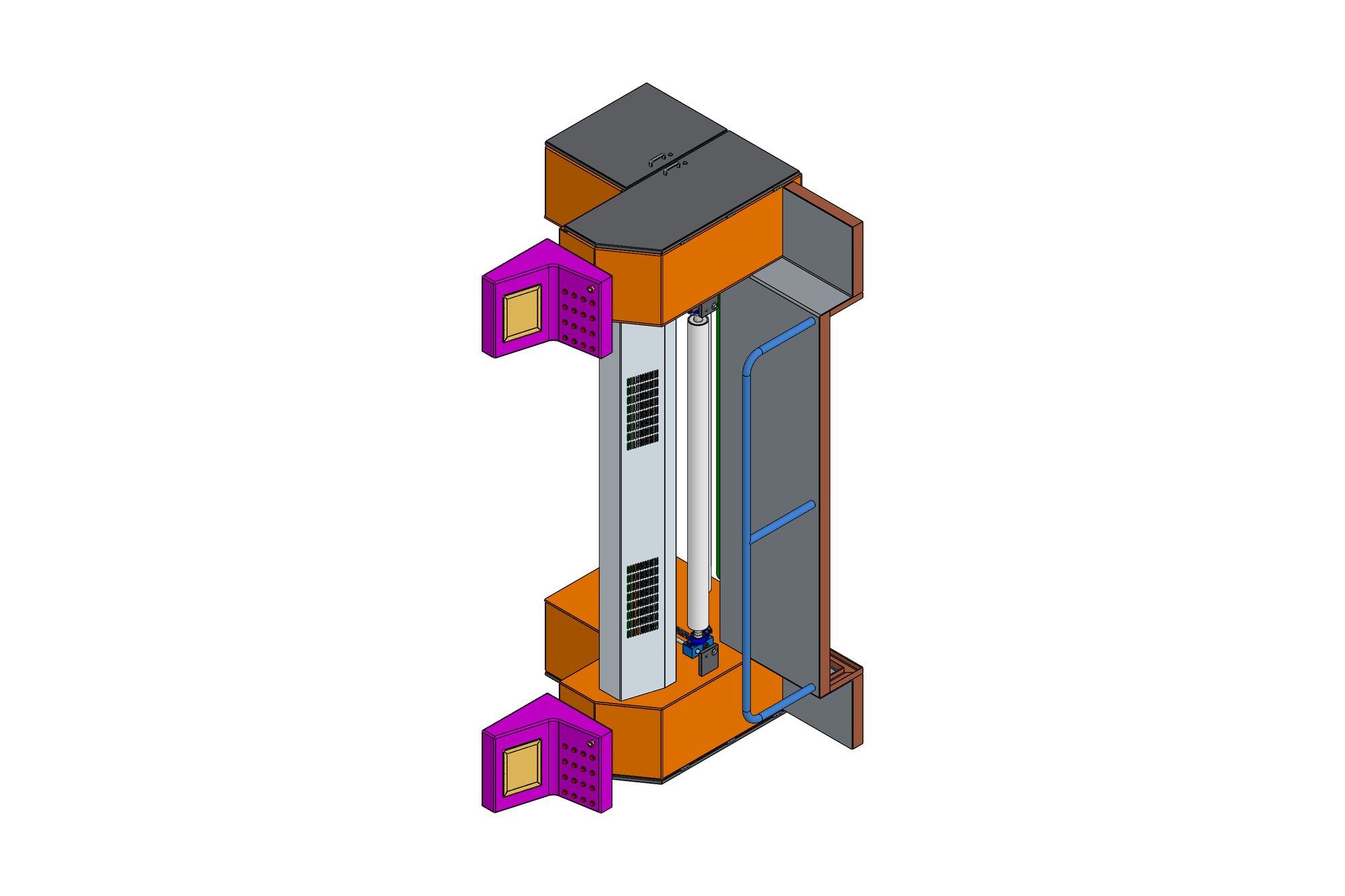
The chamber module was modelled as a Solid Edge assembly of frame, side panels, roof ducts and nozzle plates with the chain rail positioned by the fabric width (60-inch and wider configurations), then instanced five or eight times along the line with entry and exit middle frames closing the ends. The mangle assembly — trough, lifting and lowering unit, pressure roll assembly with its loading cylinders — was built to bolt to the entry frame.
The overfeed feeding assembly was detailed as its own numbered assembly (feeding frame, overfeed rollers, drive and guards) so it could be revised without reissuing the entry section. Sheet-metal panels carry flat patterns; frames carry cut lists.
Drawings were produced in DFT with the OEM's title block and tolerance table and exported to PDF and DWG, with STEP files for each section for the OEM's customers.
What was delivered
The OEM holds the 5- and 8-chamber configurations as native Solid Edge data with complete drawing sets for the chambers, mangle, overfeed and end sections, and derives customer-specific line lengths from the chamber module.
- Solid Edge assemblies for chamber module, mangle, overfeed, entry and exit sections
- DFT drawing sets with BOMs and cut lists
- Sheet-metal flat patterns
- STEP per section
Standards and conventions applied
- OEM fabrication tolerance table
- ISO 2553 weld symbols
- Third-angle projection
Have a similar requirement? Send the drawings, a sketch or a description — an engineer will scope it and reply with an itemised quote within one business day. Request an engineering quote.