- Client
- Textile finishing machinery OEM, Gujarat (name withheld under NDA)
- Industry
- Textile & Process Machinery
- Service
- Machine & Equipment Design
- Platform
- Solid Edge
- Client region
- India
- Line
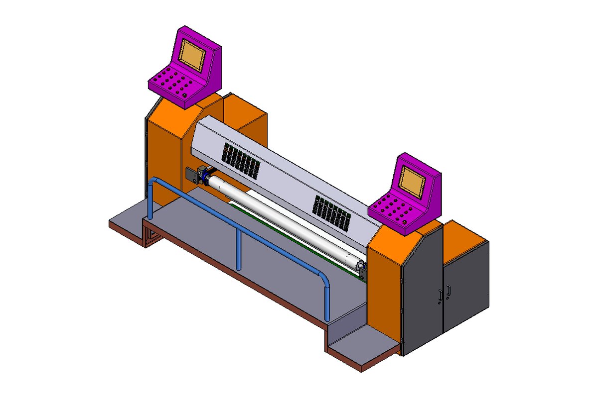
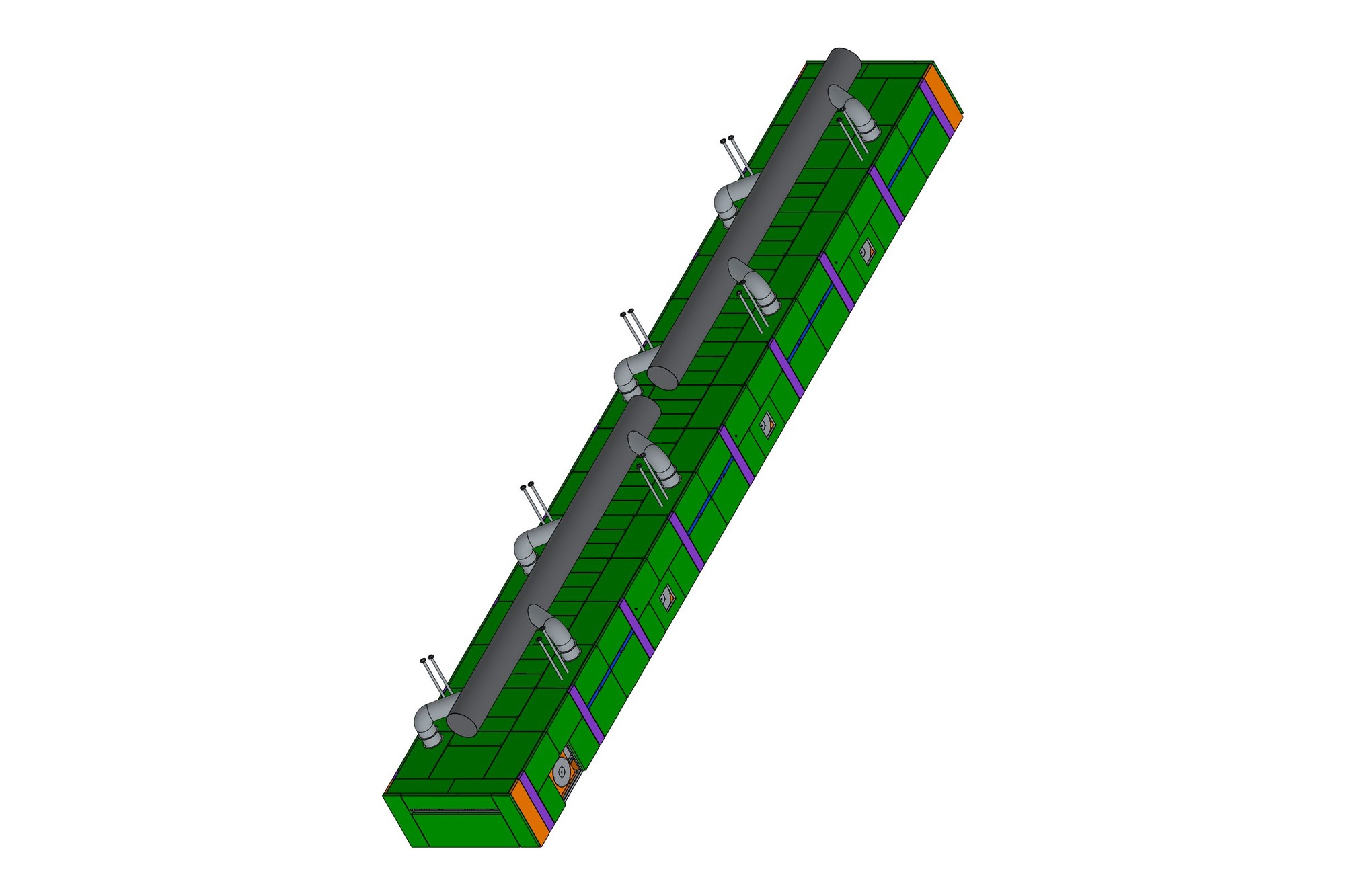
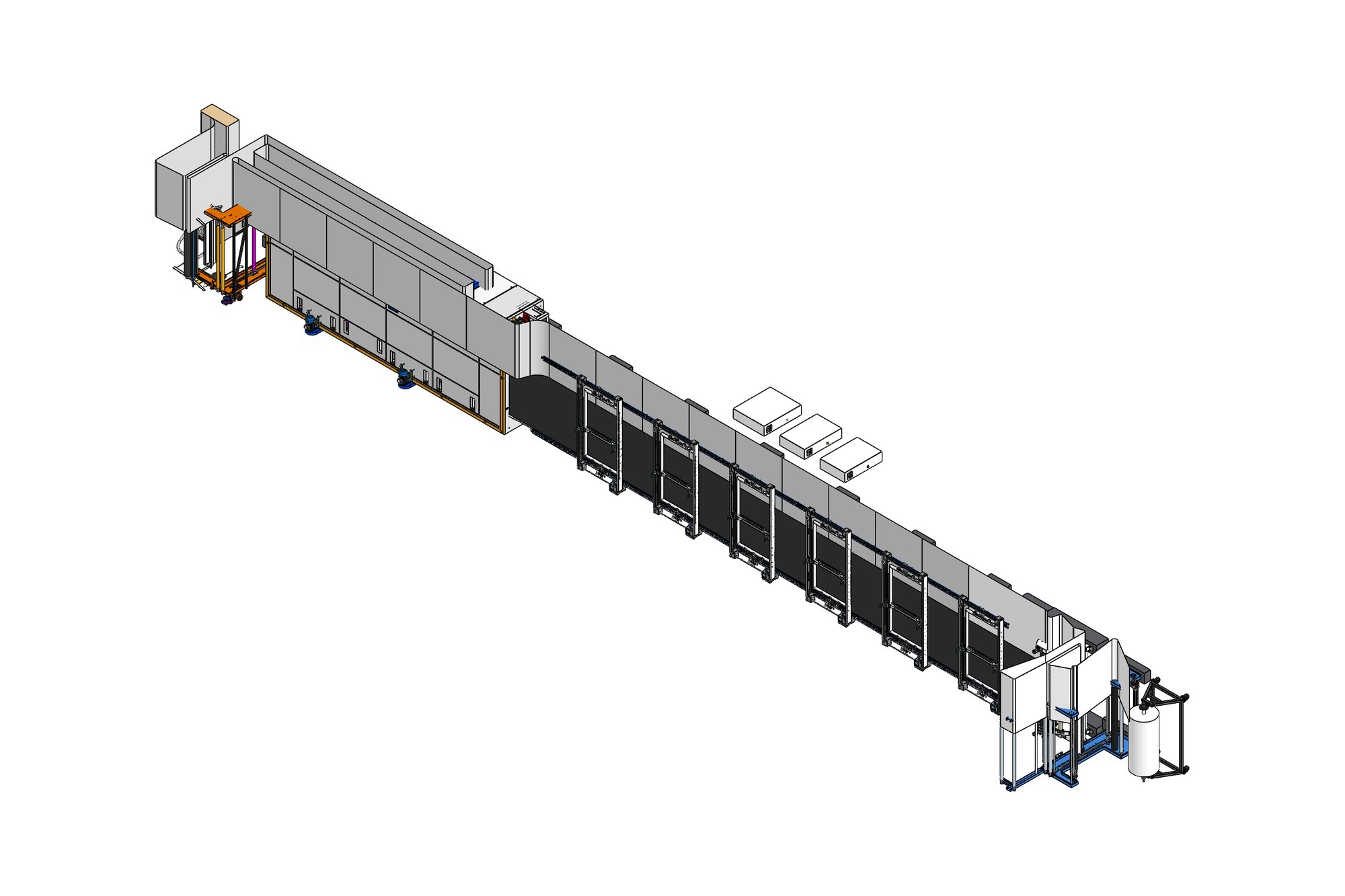
- Entry roll stand · 2 float-dryer chambers · after-washing table · plaiter wall
- Width
- 60-inch (1524 mm) fabric passage
- Model
- 250 Solid Edge sub-assemblies · chain-wheel boxes, tie rods, pressure rolls, greasing lines
The challenge
A dryer line is a machine made mostly of sheet metal and rolls: chamber walls, insulated panels, nozzle boxes, doors, rolls with bearings at both ends and the chain drives that synchronise them. Nothing is individually difficult, but there are hundreds of parts, most of them mirrored left and right, and they all have to meet at the same fabric line.
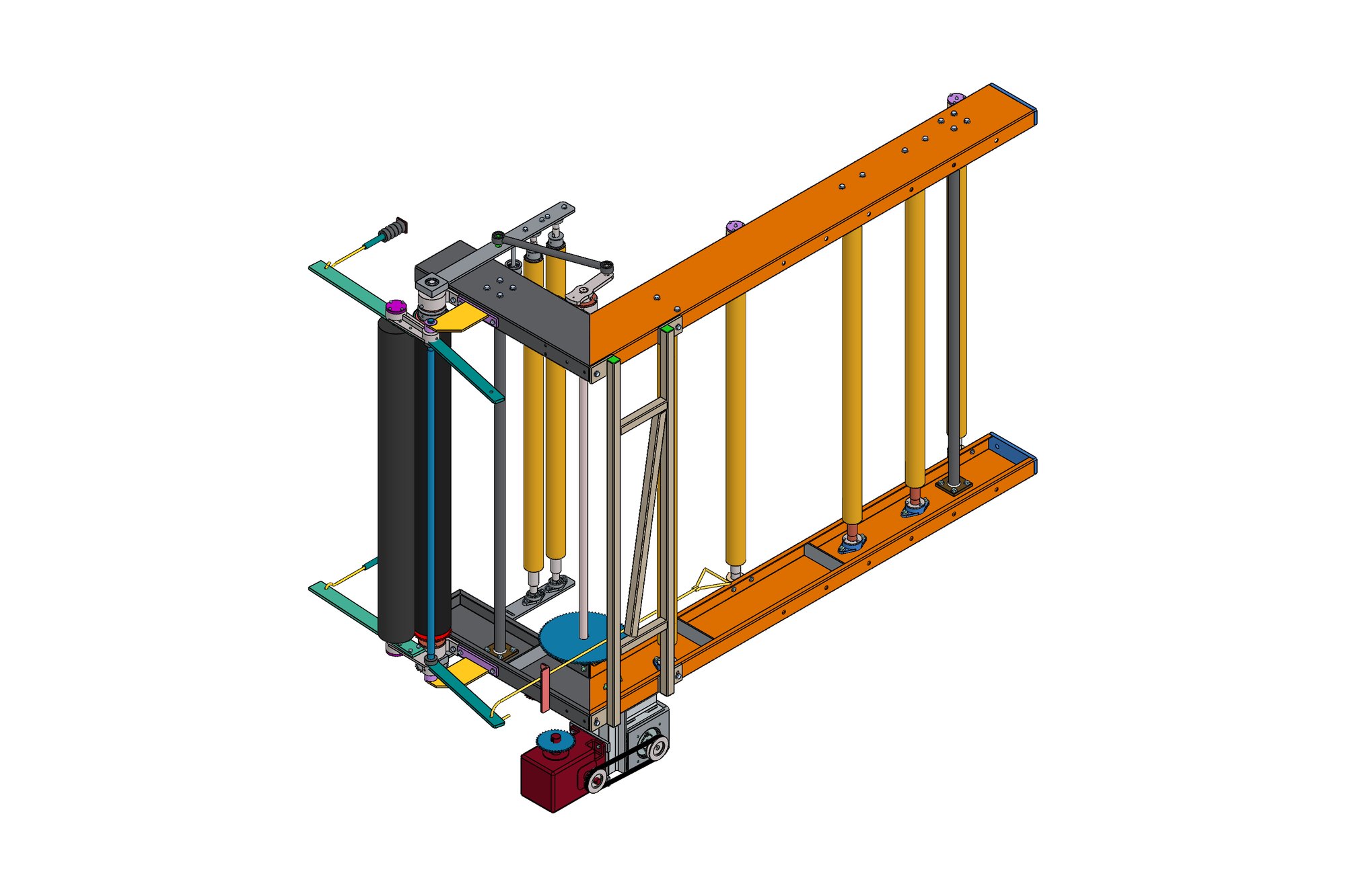
The plaiter at the exit is the one true mechanism: a swinging wall driven through a 16-tooth gear with lever and pin, lifted by a servo through a worm gear unit, with tie rods front and rear set to the 830 mm repeat. It has to fold wet fabric at line speed without creasing it.
Our approach
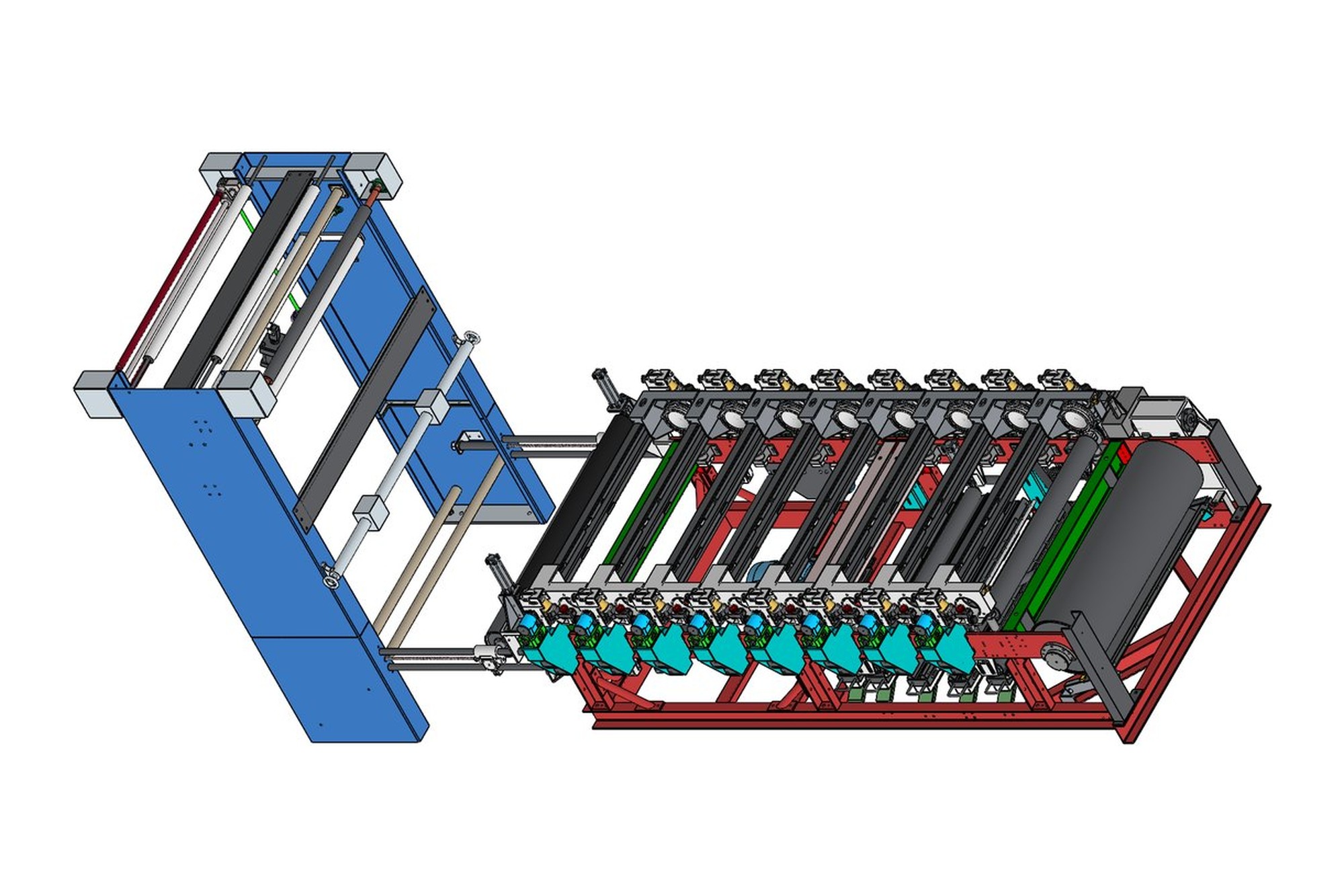
The line was built in Solid Edge as a tree of sub-assemblies that mirrors how the shop builds it: dryer entry side roll assembly, motor mounting stand, chain tightening unit, front and back side chain wheel boxes (RH and LH as mirrored assemblies), guide channels, pressure knobs, cloth pressure roll for the 60-inch width, after-washing table and the auto printing head. Each sub-assembly is a drawing with its own parts list.
Fabricated items — channels 100 × 500 × 301 and 376, 100 × 200 × 12 flats, 100 × 50 × 3 sheet brackets — were modelled as sheet-metal or structural parts so the flat patterns and cut lengths come straight from the model. Hinges, stopper pins, PVC knobs, T-T studs, couplings and rubber washers were drawn as standard parts with the OEM's numbering so the stores can issue them.
The plaiter wall was modelled as a working mechanism: the 16T gear with lever and pin, front and opposite tie rods at the 830 mm repeat, the servo lifting unit on its worm gearbox and the greasing pipes to each pedestal, and checked through its full swing for clearance to the dryer exit rolls.
What was delivered
The OEM received a complete Solid Edge model of the line with 250 sub-assemblies, fabrication drawings with flat patterns and cut lists, mechanism drawings for the plaiter and a parts register that their stores and purchase teams work from. Later line widths were derived from this model.
- Solid Edge line assembly (250 sub-assemblies)
- Chamber, roll stand and table fabrication drawings with flat patterns
- Plaiter wall mechanism drawings and parts lists
- Standard-parts register with OEM numbering
- STEP export of the full line
Standards and conventions applied
- ISO 2768 general tolerances on fabrications
- OEM part numbering and title block
- Sheet-metal K-factor and bend tables per material
Have a similar requirement? Send the drawings, a sketch or a description — an engineer will scope it and reply with an itemised quote within one business day. Request an engineering quote.