- Client
- Agricultural equipment manufacturer, Gujarat (name withheld under NDA)
- Industry
- Agricultural Equipment
- Service
- Machine & Equipment Design
- Platform
- SolidWorks, AutoCAD
- Client region
- India
- Sub-assemblies
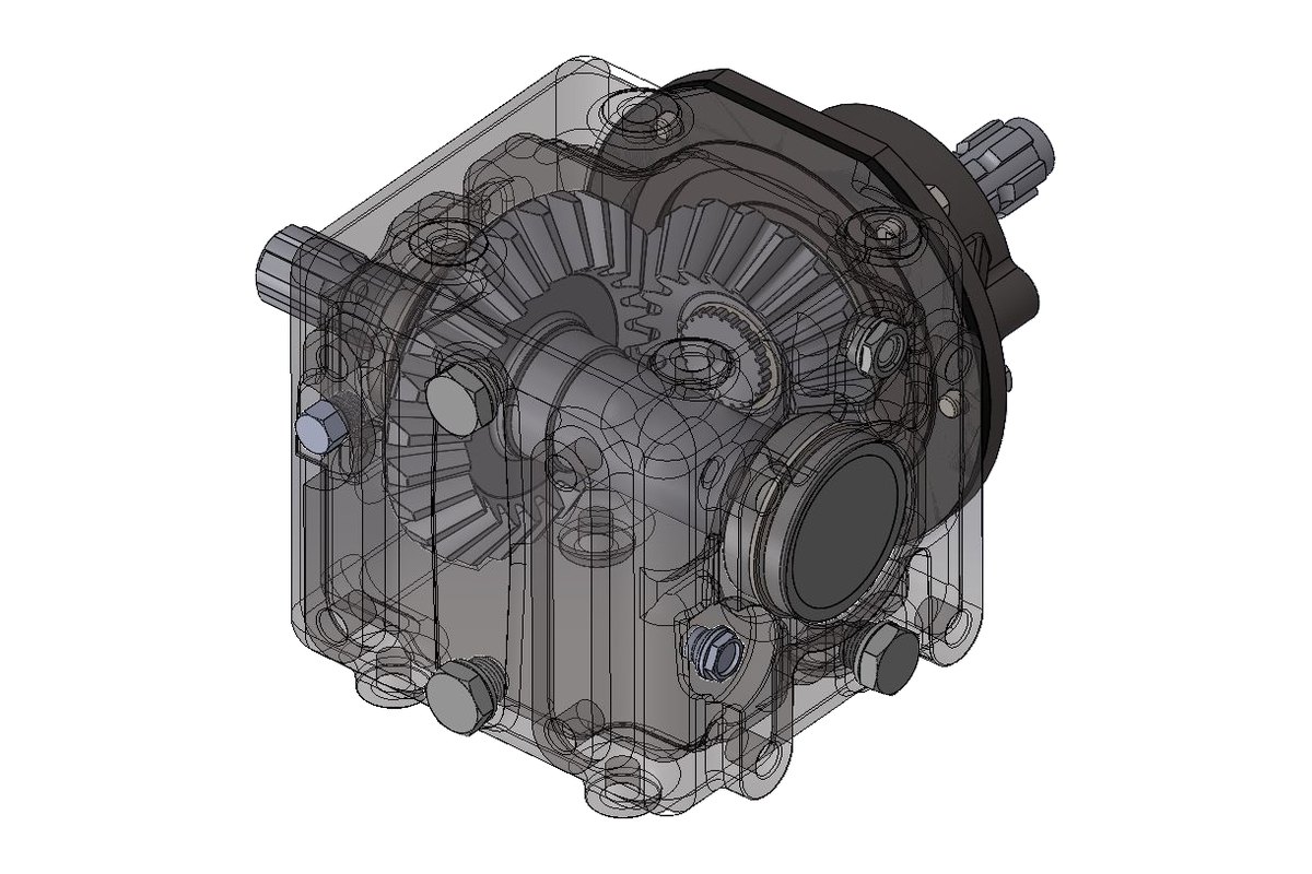
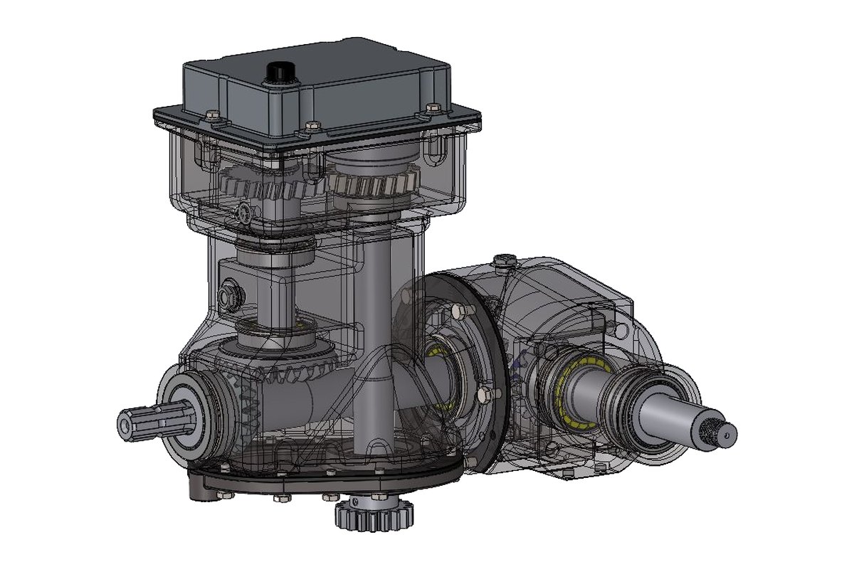
- Chassis, primary and secondary combo gearboxes, rotor, hitch
- Inputs
- Parts manual, field photographs, sample parts
- Outputs
- SLDASM, drawings, STEP, DXF, 3D PDF
The challenge
The manufacturer had machines in the field, a parts manual with exploded views and a lot of tribal knowledge, but no CAD. Every repeat build depended on the same fitters, and every improvement was a workshop experiment. They needed the machine captured as a proper engineering model that their drawing office could maintain.
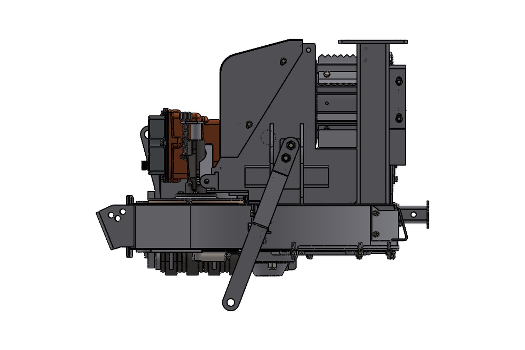
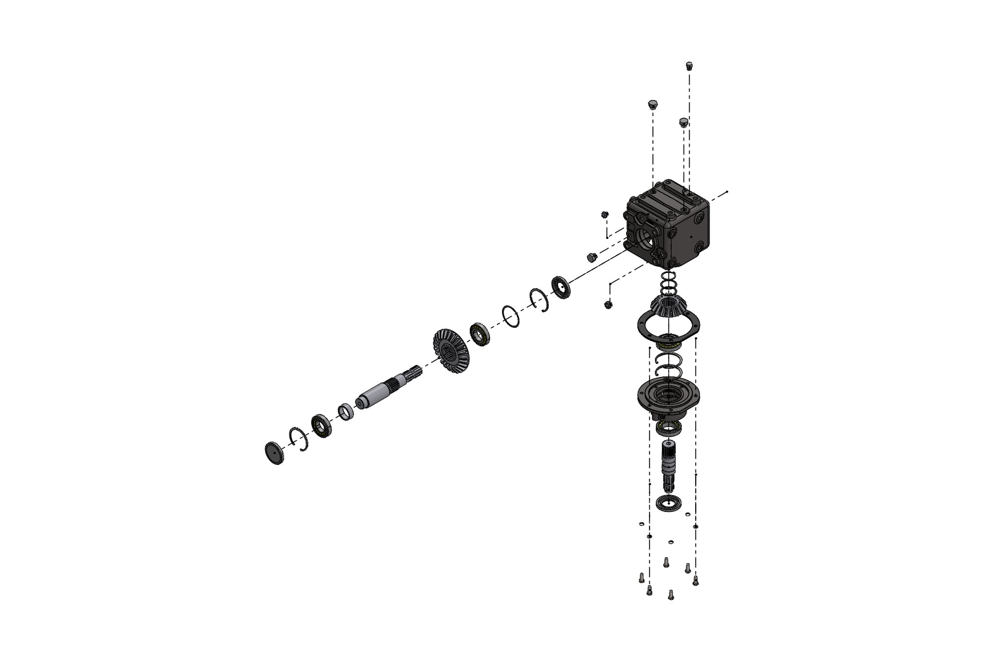
A shredder is a hard machine to document: a PTO-driven rotor running at high speed on a chassis that is towed over rough ground, with two combination gearboxes — a primary unit taking tractor PTO power and a secondary unit distributing it — that had never been drawn.
Our approach
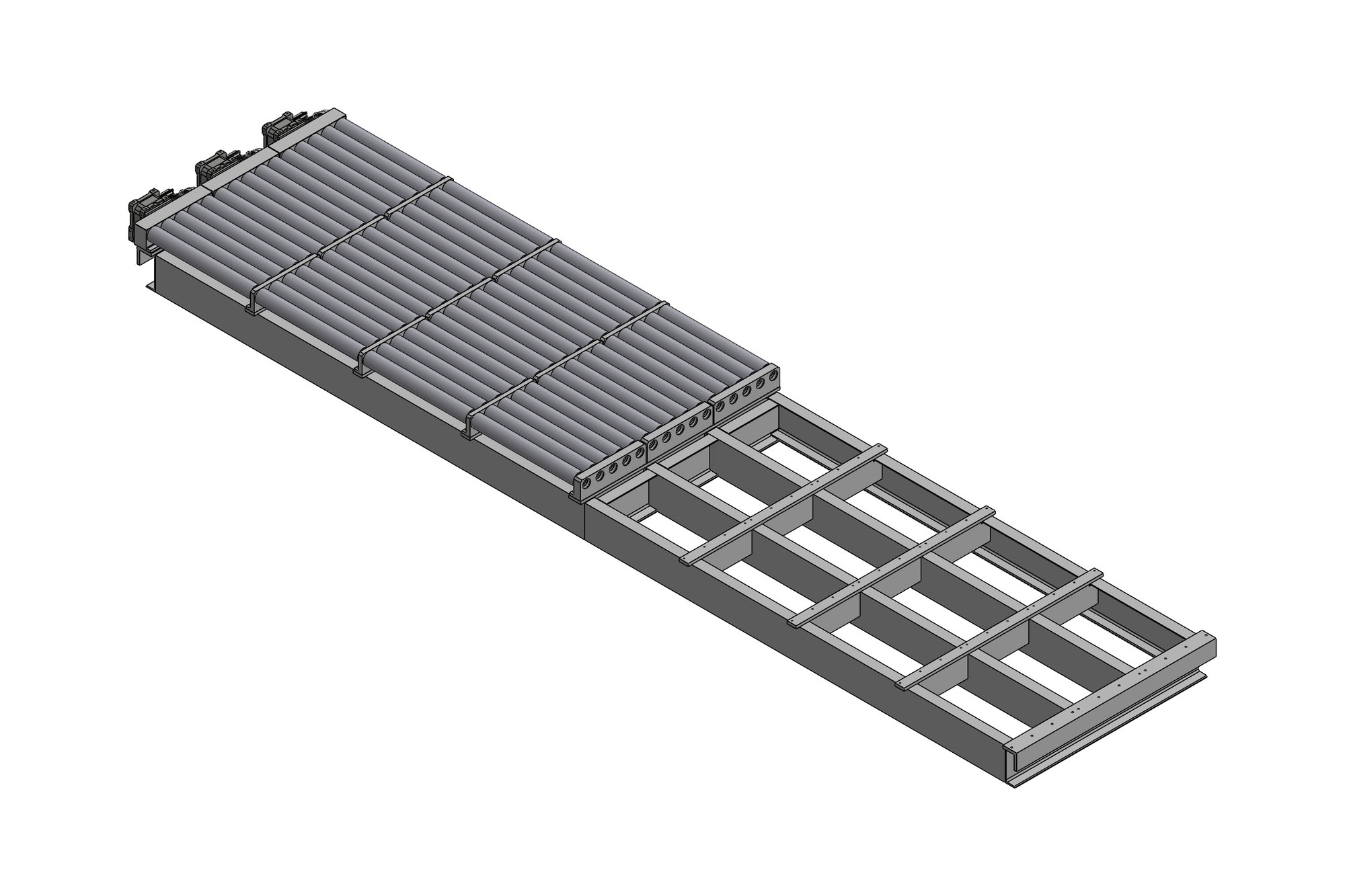
We worked from the parts manual, photographs taken on site and measurements of sample parts. The chassis was modelled as a weldment with the actual section sizes, the rotor as a balanced assembly of shaft, discs and flail mounts, and both combo gearboxes as full assemblies with gear sets, shafts, bearings, seals and housings.
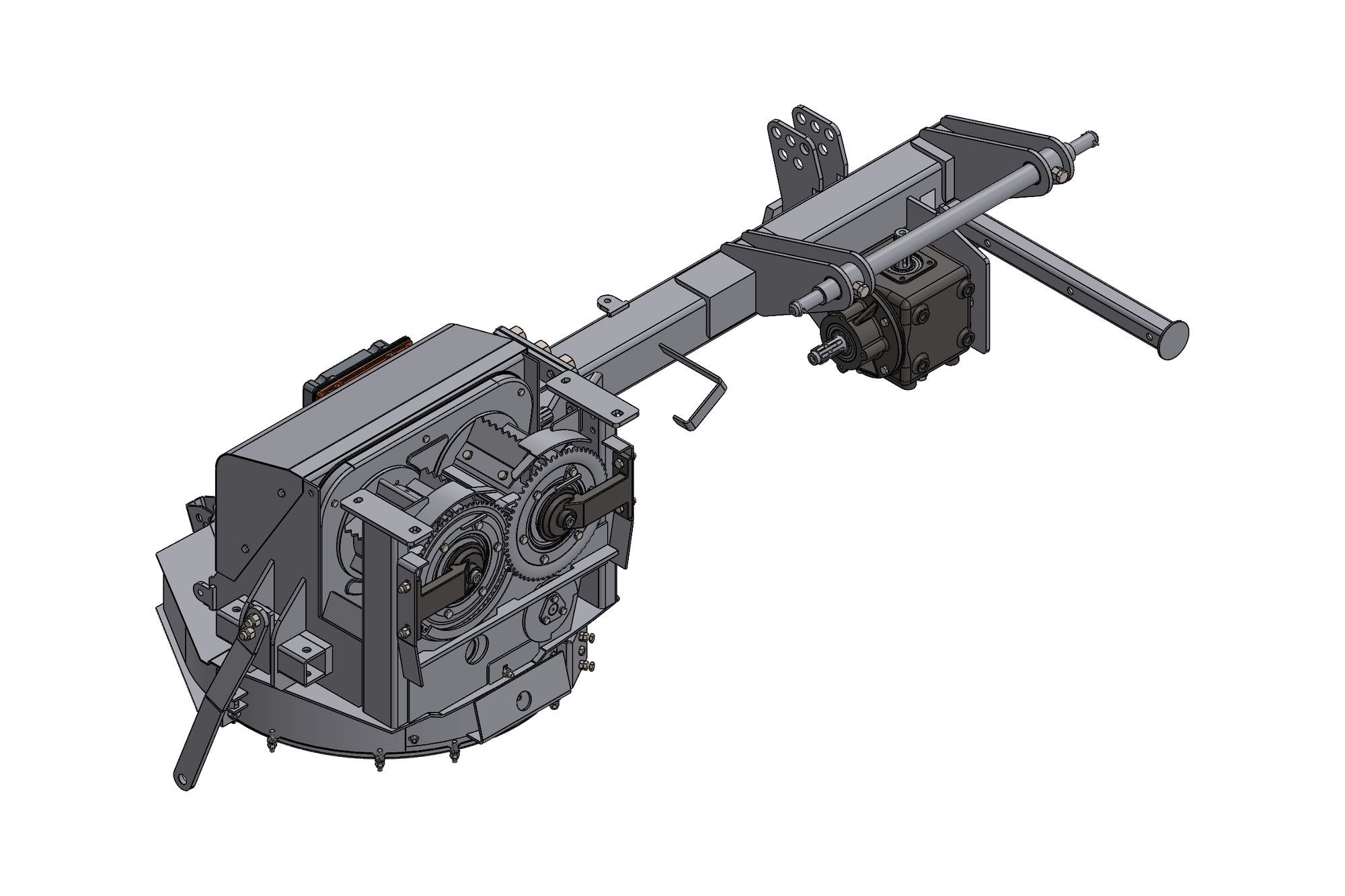
Each sub-assembly was organised as its own SolidWorks assembly inside the machine model — chassis, primary gearbox, secondary gearbox, rotor, hitch — so that the manufacturer can revise one without touching the others. Every part received a number following the manufacturer's scheme, and drawings were produced for the fabricated parts, the machined gearbox parts and the assemblies.
Outputs were prepared for every reader: DXF flat patterns for the laser-cut chassis plates, STEP files for suppliers, 3D PDFs that the sales and service teams can rotate without CAD software, and a complete set of 2D drawings with BOMs.
What was delivered
The manufacturer now builds the shredder from drawings, orders chassis plates from DXF, and has used the gearbox models to re-source bearings and seals. The complete package — more than 500 parts across the machine — is the baseline for their next model.
- Full SolidWorks machine assembly with five sub-assemblies
- Fabrication drawings and DXF flat patterns for the chassis
- Gearbox assembly and part drawings with BOMs
- STEP and 3D PDF exports for suppliers and service
- Parts list cross-referenced to the original manual
Standards and conventions applied
- ISO 2768 general tolerances
- Weld symbols to ISO 2553
- Manufacturer part-numbering scheme
Have a similar requirement? Send the drawings, a sketch or a description — an engineer will scope it and reply with an itemised quote within one business day. Request an engineering quote.