- Client
- Precision machining shop (name withheld under NDA)
- Industry
- Industrial Machinery & Presses
- Service
- 3D Modelling & 2D Drafting
- Platform
- SolidWorks CAM, Mastercam
- Client region
- India
The challenge
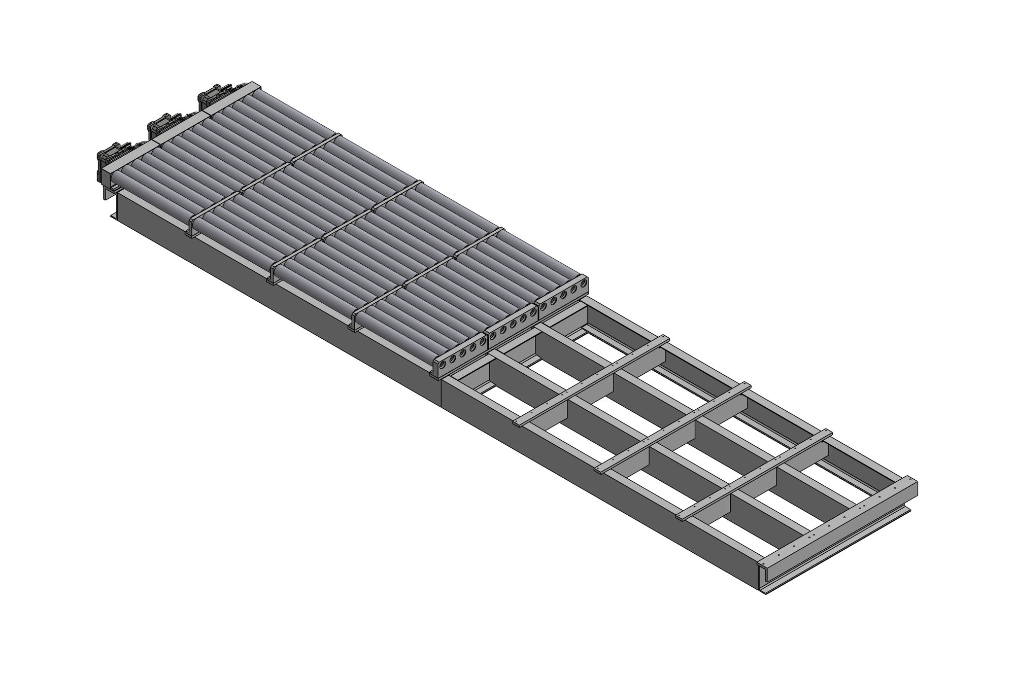
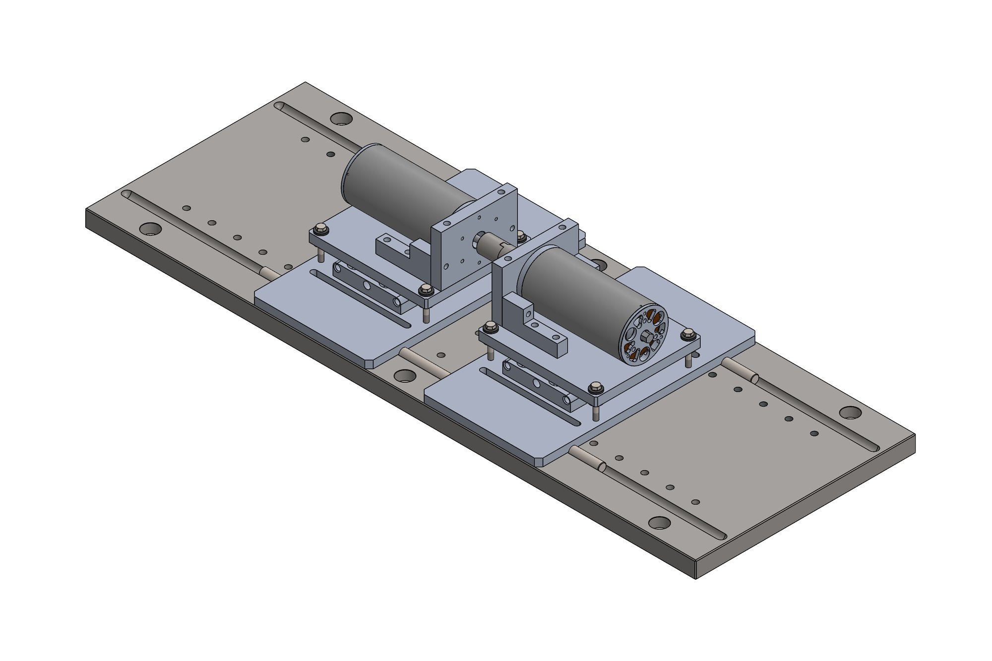
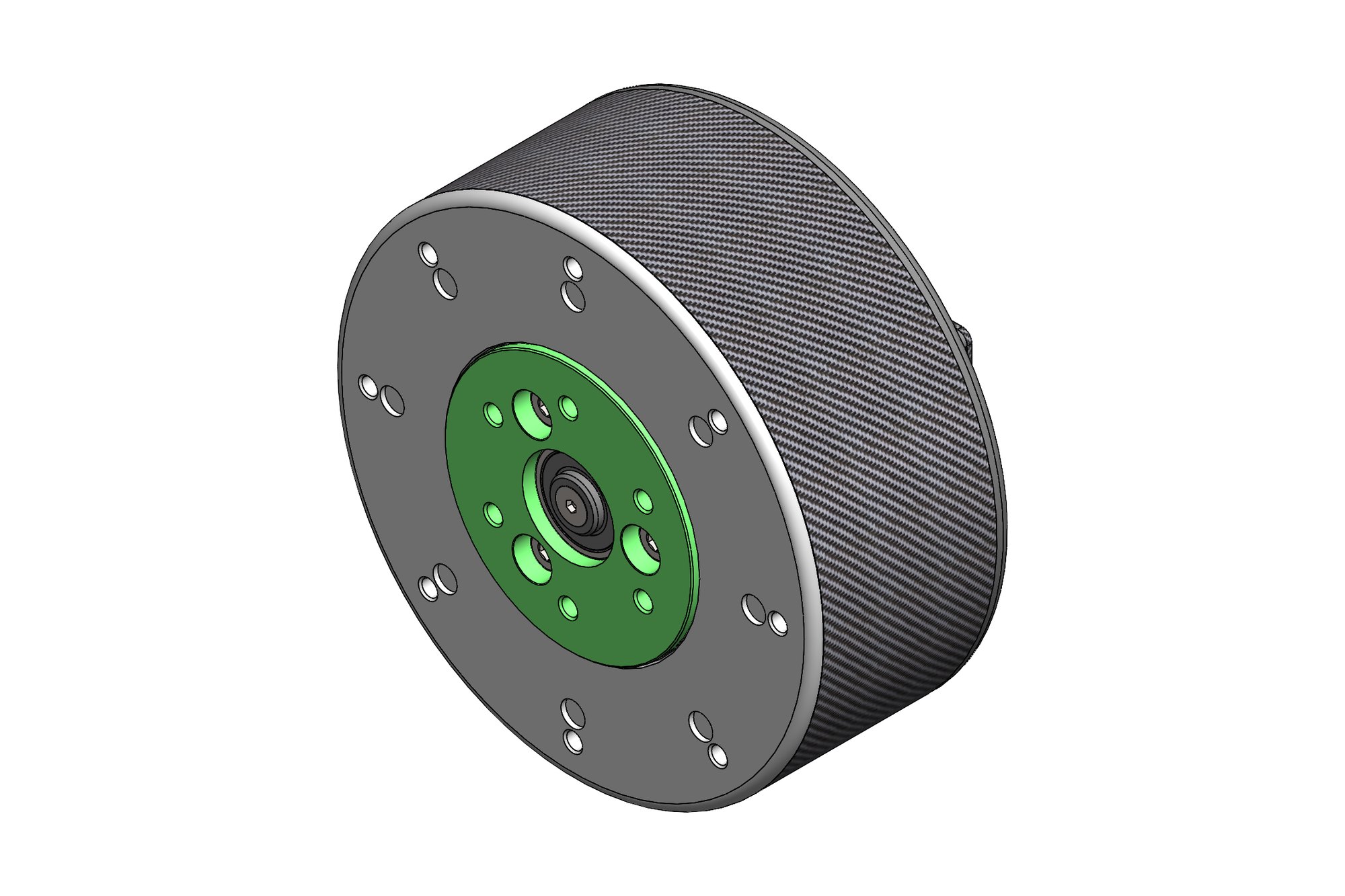
A 3D model describes the finished part. It says nothing about how to reach every surface with a cutter, in what order, or with which tool. CNC programming is where those decisions get made, and they determine cycle time, tool life and surface finish just as much as the design does.
Machining strategy
Each part was worked through as a sequence: roughing to remove bulk material quickly, rest machining to clear what the roughing tool could not reach, then finishing passes sized for the required surface. Tool selection followed the geometry — the smallest internal radius on the part sets the smallest cutter, and that in turn sets how much material the finishing pass can remove.
Verification before cutting
Toolpaths were simulated against the stock model to check for gouging, rapid moves through material and collisions with clamps before anything reached the machine. Finding a collision in software costs minutes; finding it on the machine can cost a spindle.


What was delivered
Machining strategy documentation, verified toolpaths, tool lists with speeds and feeds, and post-processed G-code for the target controller.
Have a similar requirement? Send the drawings, a sketch or a description — an engineer will scope it and reply with an itemised quote within one business day. Request an engineering quote.