- Client
- Machine-tool builder (name withheld under NDA)
- Industry
- Industrial Machinery & Presses
- Service
- Machine & Equipment Design
- Platform
- SolidWorks
- Client region
- India
The challenge
On any cutting machine, accuracy is a structural problem before it is a control problem. Cutting forces deflect the gantry and the spindle mount, and that deflection appears directly in the finished part. The design effort went into the load path from the cutter back to the bed.
Gantry and motion
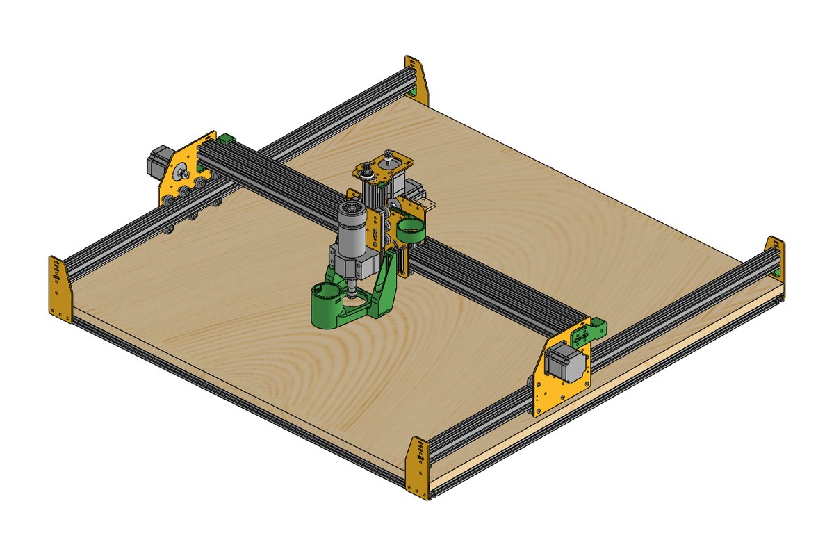
The gantry was designed around extruded profile with the linear guides positioned to keep the cutting force close to the rails, minimising the moment that tries to twist the beam. Drive motors sit at the ends of each axis with the transmission arranged so backlash does not accumulate along the travel.
The spindle mount
The spindle carrier is the last link before the tool, so any compliance there shows up at the cut. It was modelled as a short, deep bracket rather than a long overhung plate, keeping the spindle close to the Z-axis rails.
The bed
The bed provides the reference everything else is measured from. It was designed flat and supported so the workpiece sits on a known plane — an accurate gantry over an unsupported bed is wasted effort.


What was delivered
A complete three-axis machine assembly, fabrication drawings, bracket and mount machining drawings, and a bill of materials covering profile, linear guides, drives and fasteners.
Have a similar requirement? Send the drawings, a sketch or a description — an engineer will scope it and reply with an itemised quote within one business day. Request an engineering quote.