- Client
- Metal-forming machine builder (name withheld under NDA)
- Industry
- Industrial Machinery & Presses
- Service
- Machine & Equipment Design
- Platform
- SolidWorks
- Client region
- India
The challenge
Roll bending needs very high torque at very low output speed, and it needs it in line with the roll rather than offset to one side. A planetary train suits that exactly: the load is shared across several planet gears instead of a single mesh, so a given torque fits into a much smaller diameter than a parallel-shaft gearbox would need, and the output stays concentric with the input.
Stacked reduction stages
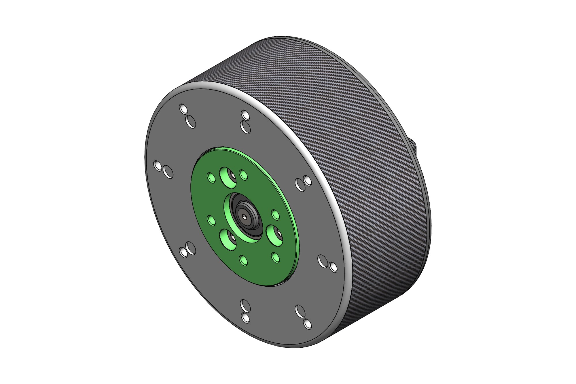
The ratio is built up by stacking concentric cylindrical stages axially, each secured to the next by a circular array of socket head cap screws. Splitting the reduction across stages keeps the load per mesh manageable and lets the ratio be changed by swapping a stage rather than redesigning the whole unit. The result is torsionally stiff in a minimal radial footprint — useful on a machine where the drive has to tuck in beside the roll.
Motor integration
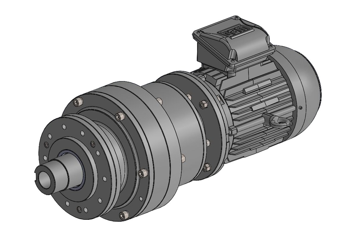
Rather than coupling to a separate motor on a baseplate, the gearbox flanges directly onto a totally enclosed fan-cooled motor. That removes the alignment problem entirely — no coupling to set up, no baseplate to keep true — and it removes the coupling as a wear item. The motor carries its own terminal box and a lifting eye, since the assembled unit is too heavy to handle by hand.
The output end
The output shaft is keyed and chamfered for a straightforward fit into the roll drive, and the front housing carries a deep pilot register with counterbored mounting holes. The pilot does the locating and the bolts do the clamping — the right division of labour, because bolts in clearance holes cannot hold concentricity on their own under the radial bending loads a forming operation generates.


What was delivered
A full 3D assembly of the geared motor, housing and flange drawings, the fastener and bolt-circle schedule for each stage joint, and mounting details for the machine frame.
Have a similar requirement? Send the drawings, a sketch or a description — an engineer will scope it and reply with an itemised quote within one business day. Request an engineering quote.